Chapter 10: Canard Wing
Yes! Finally we reach a chapter where you get to make something that actually looks like part of a plane! This chapter covers the construction of the canard wing. Normally you start out by hot wire cutting your cores. Due to the circumstances that I started with, I was able to get CNC hot wire cut cores for nearly the cost of the foam itself. The work was done by Steve at EurekaCNC and as always they look great. Steve even went ahead and designed them to have the front cut off, the 1/4" holes predrilled, and rounded the spar cap troughs so you don't have to add micro! While I don't get the satisfaction of cutting cores, I'll enjoy the accurate profiles and time savings that they afford. I can always make some model wings or something if I need to cut foam. This chapter will involve using the spar cap tape that will have some differences in the layup method.
Tips And Hints
- The drawing for the canard lift tab insert (the rectangular one) does not have the nutplates drawn in the correct positions. They should have the same 0.6 inch spacing as the lift tab. Use the lift tab to match drill. The plans say to do this, but the wording was not very clear (at least to me)
- Using the 19.0 WL from the wing templates takes the guesswork out of trying to make centerline markings for aligning cores.
- Eureka CNC cores are fantastic alternatives to making your own. If you don't have the need to make everything yourself, these cores are perfectly contoured, troughs are cut, leading edge removed, corners radiused, and holes for the dowels are already added. A very good value.
- Eureka CNC also makes a set of jigs and contour checkers. These are also perfectly made and well marked.
- Make a couple extra K jigs to use to support the foam on the long unsupported spans. It will help avoid sag/twist later.
- When cutting the UNI for the shear web layup, use 1/2" masking tape to attach along the cut line. This will hold the fibers in place and not pull out. It'll also help stabilize the fabric from warping if you have tape on both sides of the cut.
- When mounting the lift tab inserts, note that there is a slight angle to the top face of the shear web. The M drawing will show the canard at a raised angle with the lift tabs vertical. Make sure to preserve this angle as well as possible to avoid installation issues later.
- The plans show the 9-ply BID to cover the lift tab inserts to be 4" x 1.7" in the picture, but later in the plans it states they are 4" x 1.5". Cut your pieces to the 4" x 1.5" dimension. Otherwise, the plies will start to creep down over the sides and make it difficult to lay up over them without causing bumps.
- When glassing the bottom, try to put mailing tape under the peel ply to avoid it adhering to the foam from epoxy seeping through. Also, only place the peel ply along the area that needs it (0.5 inches wide).
- When glassing the spar caps, make sure to really squeegee harder than normal to ensure the fibers are spread out and packed down. Don't overdo it and create dry areas, but it will take extra work to get the proper amount into the trough. Squeegee till you don't get extra epoxy to come out (like the final layer of a normal layup).
- To check if the spar cap has been filled correctly, use the countour checker and go along the surface from the center to the edge and find the spot where epoxy starts to pick up. I added electrical tape to protect the surface and added an extra piece over the spar area to account for the thickness of the masking tape. This allowed me to perfectly fill the spar cap without having to shape it further.
- It is possible to get all three UNI pieces for the final skin layup from one length of fiberglass. Here's what I did:
- Layout the glass on the table (all 12 feet). Straighten the fibers as well as you possibly can.
- Take a piece of paper and check the length you need to wrap from the point 2 inches onto the bottom layup to the trailing edge. This will tell you the minimum amount you need for the first layup. I believe mine was 13 inches.
- Using the narrowest masking tape you can get (I had 3/4 inch), measure from the selvege edge up to the amount you found in step two and add 1 or two inches. Place the tape edge at this point. Use a right angle ruler to place the tape at this same distance the entire length of the glass.
- Place the next strip of masking tape the same distance as the first minus 1 inch. Verify that the final layer has enough to reach where needed. My fabric widths were 13 - 12 - 11.5 inches. The first layer was close while the last had a lot of excess, so you can adjust as needed.
- Cut down the middle of the masking tape. The tape will hold the fibers together.
- Lay up each layer as directed. I used the selvege edge on the bottom wrap around for the first and last layer. The third layer I had to cut the tape from the edge (both edges will have tape). This will make a bit of a mess, but if the fibers are dabbed in place with epoxy they tend to stop coming out.
- Trim the excess at the trailing edge when done.
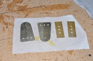
So I started off by making the lift tabs and inserts. For some reason I decided not to buy them premade from the Cozy Girrls. Maybe I just felt like proving I could do it and these were simple enough, or I was just trying to save some money. Either way, they weren't too bad. The lift tabs must be free of scratches and nicks to ensure no stress areas are created. I cut and drilled both parts from 1/8" 2024-T3 aluminum. The edges were all polished to remove jagged cut marks and the holes were deburred. I drilled and counter sunk for the rivets to hold the nutplates onto the insert. Once all cutting and polishing was done, I cleaned and alodined the parts.
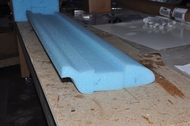
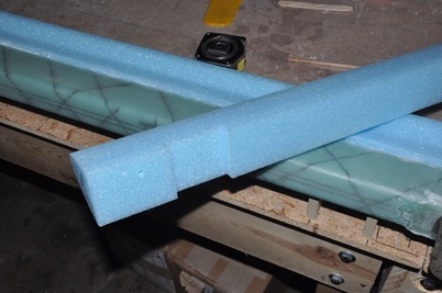
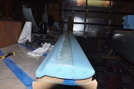
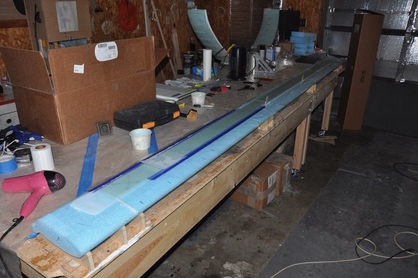
Next, I broke out the wing cores that have been boxed up for a long time to stay pristine. They are beautifully cut with perfect looking contour. I got out the separate parts for the canard (one inner core, two outer cores with the troughs cut, and two outboard edges with no trough). The cores come with the troughs pre-rounded, the shear web pre-rounded, the leading edge already cut off, and the 1/4 inch dowel holes pre-drilled. Very nicely done.
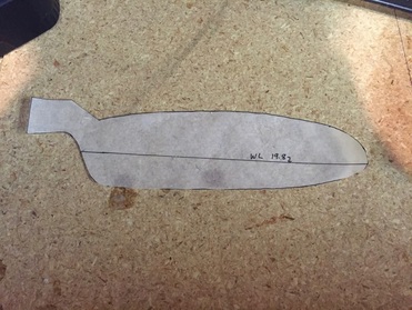
First thing you are suppose to do is draw a centerline along the top of the shear web area (where the leading edge was cut off) to use for aligning the cores. Problem is, the troughs aren't symmetrical on both sides of the canard. I tried several times to figure out a way to draw a centerline. The center core was easy since it doesn't have any taper to the troughs. However, the outer cores aren't as straight forward. After trying some various methods, I decided to look at the M-drawings to see the core templates. Lo and behold there's a 19.8 WL drawn on every core. It's not in the center, but it's a common mark across all the cores. The only place I could see where the centerline was needed was on the center core for positioning the lift tab inserts and that was the easiest centerline to draw. So I marked each core with the WL using copies of the cutout templates. This made a definite line to use for aligning the cores with no question about straightness.
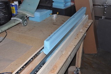
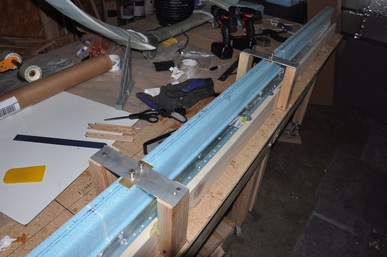
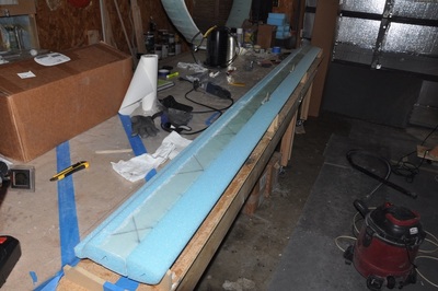
With the WL marked on the shear web area, I then started prepping for the shear web layup. First thing was to level the 12 foot table as best as possible. I used my self leveling laser to check the level of the table along with my smart level. Next, I used two 2x4 boards to attach to the table for resting the cores on. The cores get covered with tape along the surface just below the trough cutout to keep epoxy from dripping onto the foam surface. I decided to follow Wayne Hick's suggestion of using angle metal strips to clamp the canard into place. First I attached the 2x4 boards with bondo but I separated them by 3 inches (plans uses 3.5 inches). The cores are about 2.75 inches wide, so this allows enough room. Then I used my laser level to figure out where to sand the boards down because despite buying straight boards they warped when I got them home. I bought some corner re-enforcements from the dry wall area that were a 90 degree bend and had holes predrilled. I attached one of these strips to one side making sure it stuck out past the board edge a bit where the cores go and was as straight as possible. I attached the other in a way that the core would be slightly snug to help hold it in place. As a backup, I added finishing nails to rest on the edge of the strips. The strips will help clamp the pieces in place and keep them as straight as possible. The nails will give me a solid hold once they are glued in place.
I trial fitted the cores with the nails in place to make sure everything was flat, level, and lined up correctly. Afterwards, tape was put along the metal strips where the cores meet so that they don't glue to the metal. I used hot glue to attach the nails to the metal strips for the center core only. This will secure the core so it won't move. Recheck for level. With the center core fixed in place, the other two cores are attached to the center core by applying dry micro between them, pushing them together to squeeze as much out as possible, then removing the excess. I also took it a couple extra steps and taped the joint to help hold things down and in place. After getting the core positioned, I hot glued the nails on the core to hold it in place and allowed it to cure.
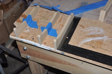
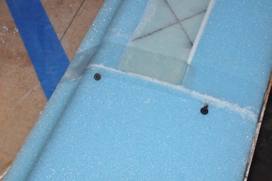
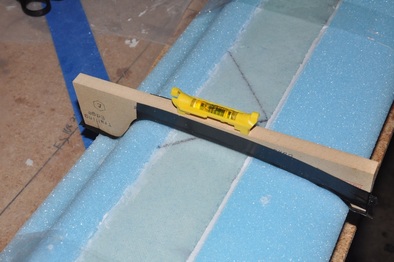
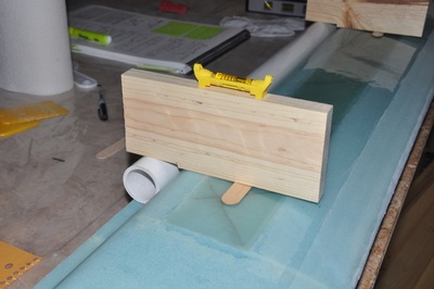
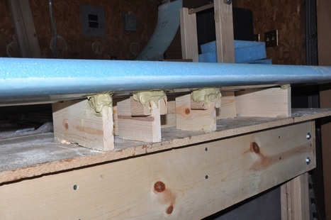
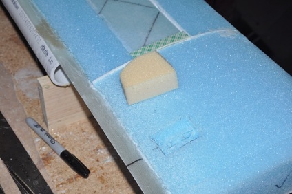
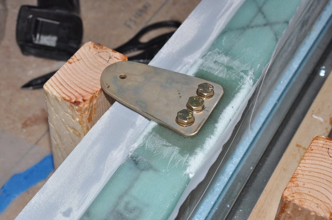
After cure, I worked on the lift tab inserts. First you mark out the location of the center for each tab (15 inches from the core center). Then I marked out the space for the tab and removed enough foam to inset the piece so that it was flush with the foam surface. Afterwards, I made four blocks of wood that were tall enough to stand on the table and be level with the foam surface top. Using strips of aluminum, I cut them out to span the two blocks then using the insert I match drilled the holes into the strip. The idea is that the strips will be secured in place and hold the insert level with the foam and will later guide where to drill out the holes after glassing. After getting the strips positioned so that the insert was placed correctly, I drilled the secure holes to screw down the strips.
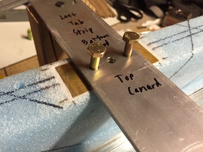
Next was to attach the inserts into place. I mixed up some fairly dry micro, then spread it onto the nutplate side of the insert but making sure not to go past the holes in the nutplates. This was then pressed in placed, the excess removed, and the locating strips with release tape added installed. I verified the holes didn't have micro in them and added the bolts to clamp the insert into place.
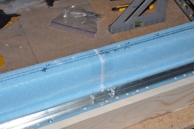
To keep epoxy from getting into the holes, the plans tell you to add silicone to cover them up. Reading about the horrors of getting silicone on parts and having adhesion issues, I decided to go with acrylic sealant. I used black colored sealant, though white might have been a better choice for visibility. I used enough to just cover up the holes then scraped them flush and removed the excess from the insert surface. This was left to cure. The other prep involved using masking tape to cover the trough edges so that epoxy wouldn't drip into them. I tried to use other tape with more resilience, but I couldn't get them to stick as well, so I used the masking tape. I also drew several 45 degree alignment marks along the entire surface of the layup area.
Next up is the very large shear web layup. I had to do this one by myself, so for reference it took about 6 hours to do. I had cut out all my fabric for this layup ahead of time:
- 9 pieces of UNI 10" wide cut full length at a 45 degree angle
- 1 ply BID 10" wide cut at a 45 degree angle
- two sets of 9 ply BID 4" x 1.7" (this should have been 1.5", see tips and hints at the top)
- two sets of 1 ply BID 8" by 4"
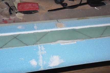
Next up is removing the peel ply and checking the layup. Everything look fairly good. I had some rough edges to sand off, especially around the lift tab inserts. I reattached the metal strips that locate the holes and started to slowly drill out the glass. The acrylic made a nice drill stop when I broke through the glass. To get the acrylic out, I used a dry wall screw to screw into the material, then just pulled it out. Most of the material came with it only leaving a couple of small bits. I also drilled out the holes for the wooden dowel locators.
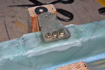
Next the lift tabs that I made earlier are permanently installed. This is done by using wet flox to attach the tab to the inserts using three AN4-7A bolts and a washer. I had to use a thread tap to clean out the threads slightly from all the stuff that was in there to get the bolts to grab properly. I first sanded the fiberglass surface (even though I peel plied, I always sand for that much better of a bond), sanded the tab with 220 grit as specified, then made up some wet flox, smothered it on the contact area on the tab, then installed it with the bolts. The bolts were tightened to about 55 lb-in each. Note that nutplates are slightly out of round so the bolt will be stiff getting it to completely seat. After torquing down, I scraped away all the excess flox from the surface making sure nothing was left on the lift tab then allowed to cure.
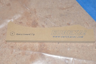
This is a good point to admire the fine work that Steve does at Eureka CNC. These are the new wooden jigs that he now routes out. They are all labeled and very well made. I bought the entire set of jigs for both the canard, wings, and winglets and I'm glad I did. Like his cores, these are very well made, are nearly perfect, and cut down on your build time considerably. It's like getting some quick-build parts for a plans built plane, but you're still doing a lot of your own work. I highly recommend these jigs and you will see more of them as time goes on.
UPDATE
I recommend making at least two extra K jigs. These will be used to support the foam along the span that is unsupported on both sides of the canard. I had some sag and twist in these areas and the extra jigs would have helped.
UPDATE
I recommend making at least two extra K jigs. These will be used to support the foam along the span that is unsupported on both sides of the canard. I had some sag and twist in these areas and the extra jigs would have helped.
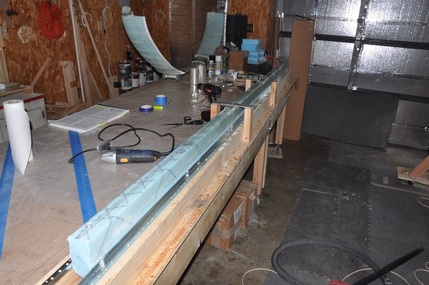
Next I removed the canard core from the holder, pulled all the nails out, and removed the jig. I trimmed up any material that lapped onto the trough sides so that the spar cap would like evenly. Next step was to verify the table was level and straight again. I used a couple of levels to check the surface with and adjusted as needed. With the table level, I marked the locations for the jigs. Using a square and a laser line, I made sure all the jigs were lined up properly. I taped them into place to check them. Afterwards, I used hot glue to bond them into place once I was happy with the alignment.
Next I got my 12 inch drill out and drilled out the dowel holes from inside the wing core. Then I inserted the dowels till the end was flush with the back curve of the wing surface. Trial fitting the center leading edge allowed measuring the foam that needed to be removed to make room for the lift tabs. I used my table saw set at the right height to pass the foam back and forth over the surface to get a nice even cut. A little sanding corrected any unevenness.
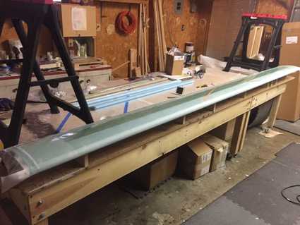
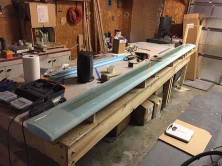
With the center leading edge attached, I fitted the other two leading edges on. The foam was checked for straightness and match between cores. minor adjustments got them to fit will. It's starting to look like a wing! I laid the core onto the jigs and was rewarded with a mostly flat canard. One end bowed up just slightly, but should be able to be weighed down into place.
With everything fitted, I removed the leading edges and mixed up dry micro. The dowels were inserted with micro (though most gets wiped off by the foam, still plans instruct to do it), then the leading edges were pressed on to squeeze out the micro. I filled in the area around the lift tabs with micro as well. I removed the excess, radiused the micro in the spar trough corner, then used tape to wrap the wing in order to hold the pieces in place better. The outboard cores were attached with micro, then I used dry wall screws to hold the pieces on. I taped the joint to help keep the micro flush. I did not glue the canard down at this time because I wanted to get to the other side to remove excess micro. Instead, after getting everything cleaned up, I weighed it down in the jigs checking that it was straight. I left it to cure.
After cure, I removed the tape and checked everything out. All looked good, so I committed to gluing down the canard with small dabs of 5 min epoxy. I checked out the alignment of the canard and it was still level and any twist was less than 1/8 of a degree, probably within measurement error.
After gluing the canard down, I checked the straightness by sight and by level. The leading edge bumps out just a small amount right in the center. I didn't sand down the core in the middle to account for the extra plies in this area. I decided to leave it alone because ultimately it's inside the fuselage and will not matter. Guess I won't have the 'perfect' plane anymore (as if I had it to begin with anyway).
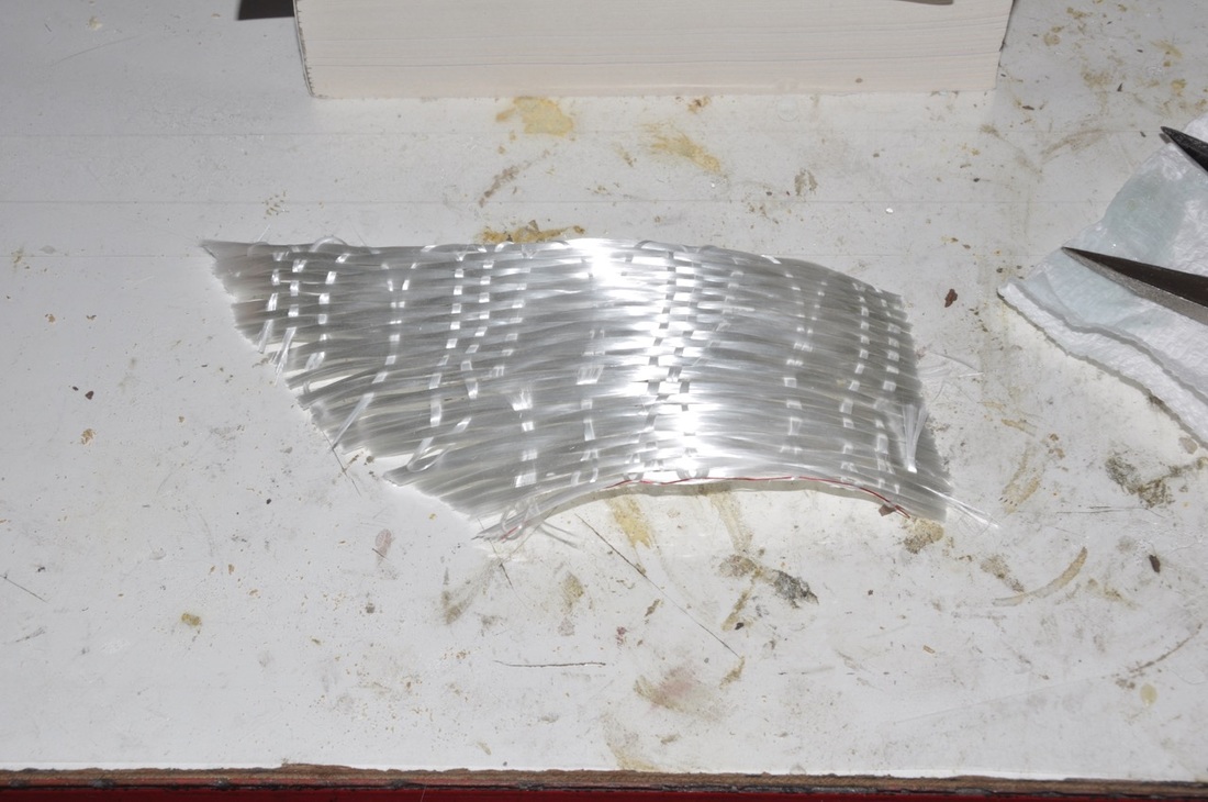
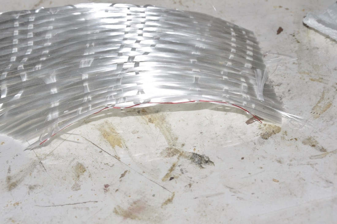
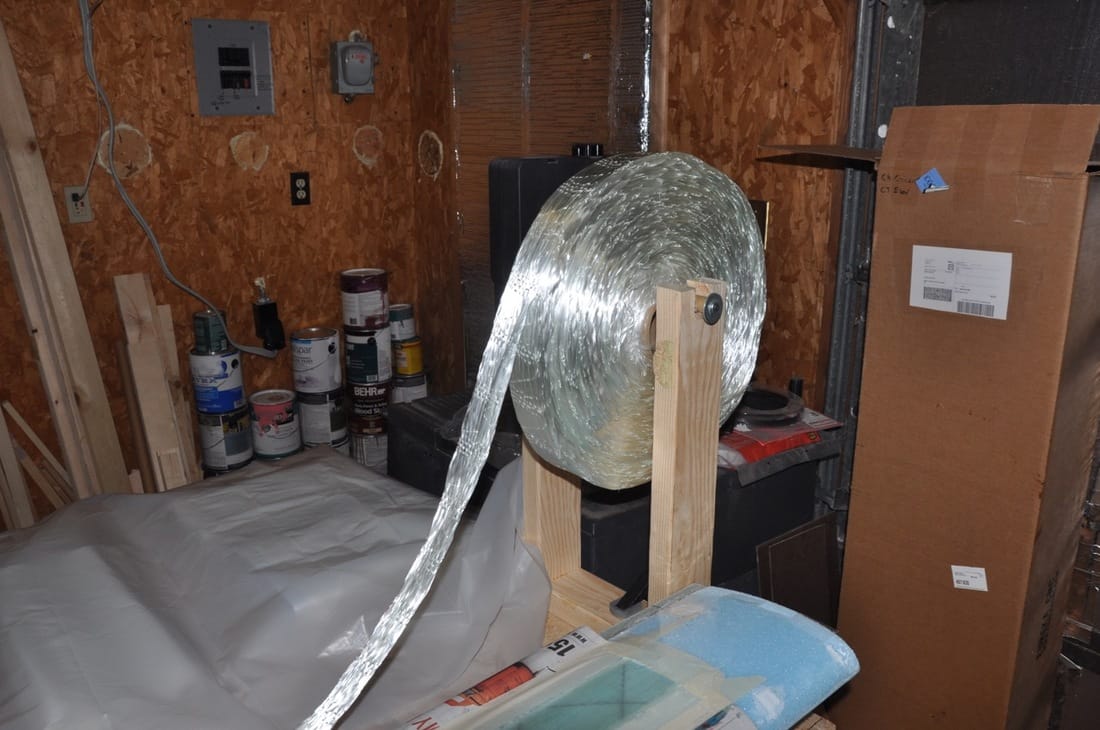
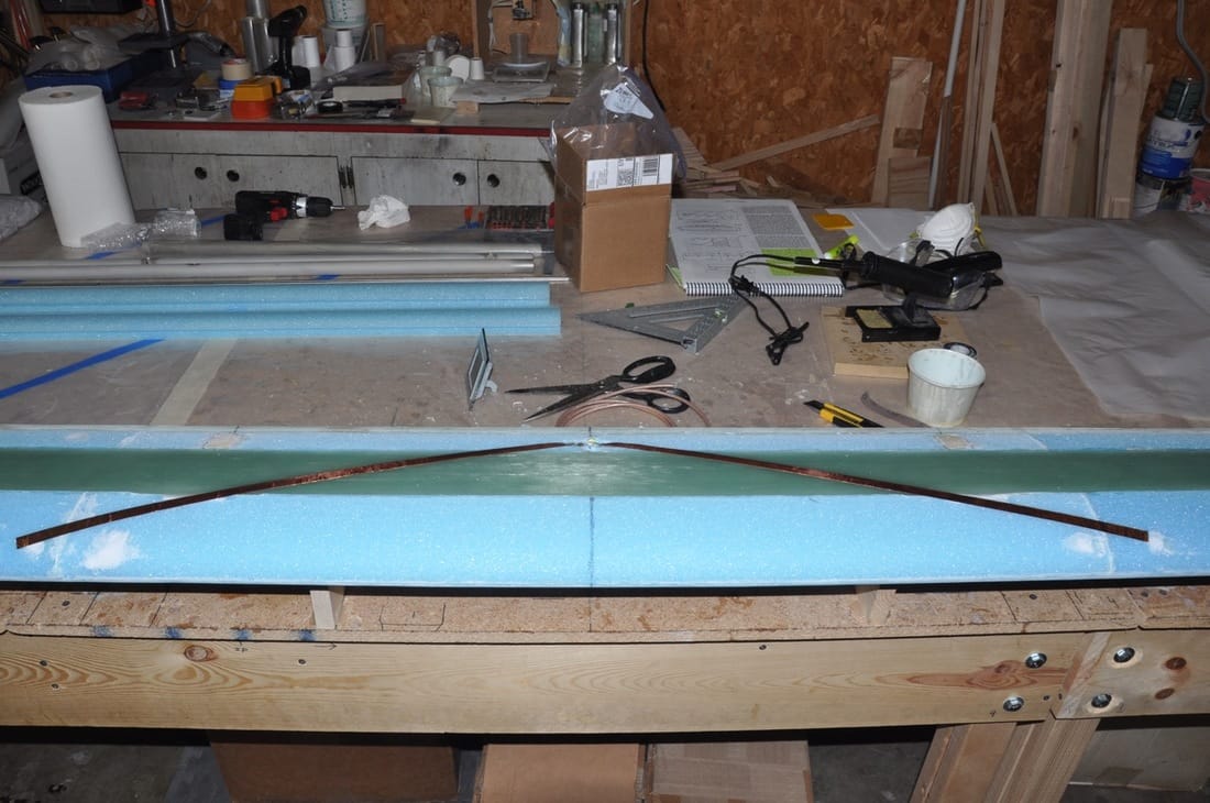
Next up, I prepared for the spar cap layup. I made a holder to dispense the tape from. For those that have never dealt with this type of glass, spar cap tape is a UNI type of glass that is a bit thicker than your cloth type. It's held together with a series of cross threads that are held in with a polyester key thread. For the tape I had, the key thread was red in color so easy to see. To use spar cap tape, you cut out the length you need, press it into place on some epoxy, snip the red key thread in the center of the tape length, then pull the thread out from the ends. This helps to pull the UNI threads in the direction that will make them straight. Once the key is removed, the cross thread is removed by pulling it from the ends towards the center. It helps to hold the fibers down that no longer have a cross thread while removing the cross thread so they don't get pulled in different directions. After that, it's a matter of wetting the fibers out and straightening them. To straighten the fibers, I took a comb and cut it to the right length. You then start at the ends of your tape and work your way towards the center pulling it through the fibers to straighten them and help them wet out. To help the fibers not create a bump, the ends are cut at a 45 degree angle so they slowly blend in with the surface. I made the angle go towards the rear of the canard because it seemed to be slightly shallower on that side, but I think it doesn't matter in the end.
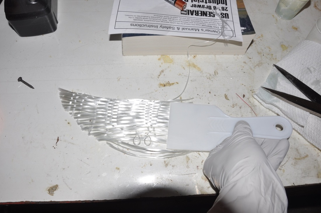
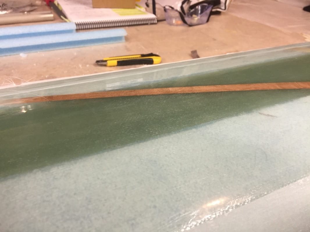
Before starting the layup, I lightly sanded the shear web to make a nice bond between it and the spar cap. It took about 3.5 hours to wet out the spar cap tape on my own for the bottom. I used 6 plies, which appears to be right in line with what most people get. What I did was cut the first piece full length and with square ends so it went right up to the edge of the trough. I prewetted the trough, then placed the tape onto the surface. The wet epoxy helped stabilize the fibers. I cut the red key thread in the center, then pulled it out at the ends. I then removed the cross thread from the end to the center. This all helps keep the fibers straighter. Next, I mixed up some more epoxy to pour on top. I spread it out, then using the comb I cut to size and the putty knife, I started at the fiber end and pulled the comb through to straighten the fibers while holding them in place with the putty knife. I kept working towards the center, then restart over on the other end till the whole thing was straight. The comb helped to wet out the fibers. Be warned, spar cap tape is harder to wet out. I then took my taped contour template and dragged it along till I found the spot where it would pick up epoxy signifying that was where the trough was full. I then marked that location and did the same for the other side. I could then cut the next piece of tape, but this time the ends were cut at a 45 degree angle to help it blend. Repeat the process till the spar trough is full everywhere. Remember that bumps in the center aren't as critical due to being in the fuselage. Once I was done filling, I peel plied the surface (wasn't going to skin it that night without help) and used the contour template to drag over the surface to help shape it properly. It was left to cure.
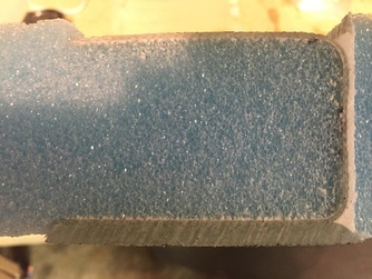
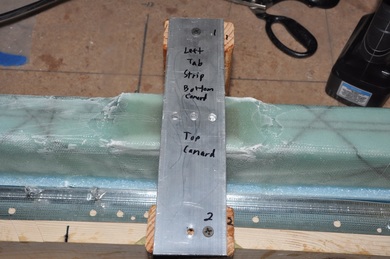
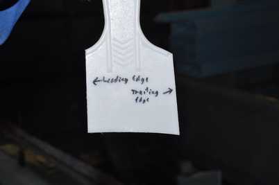
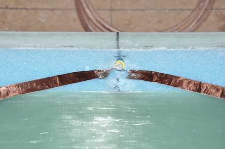
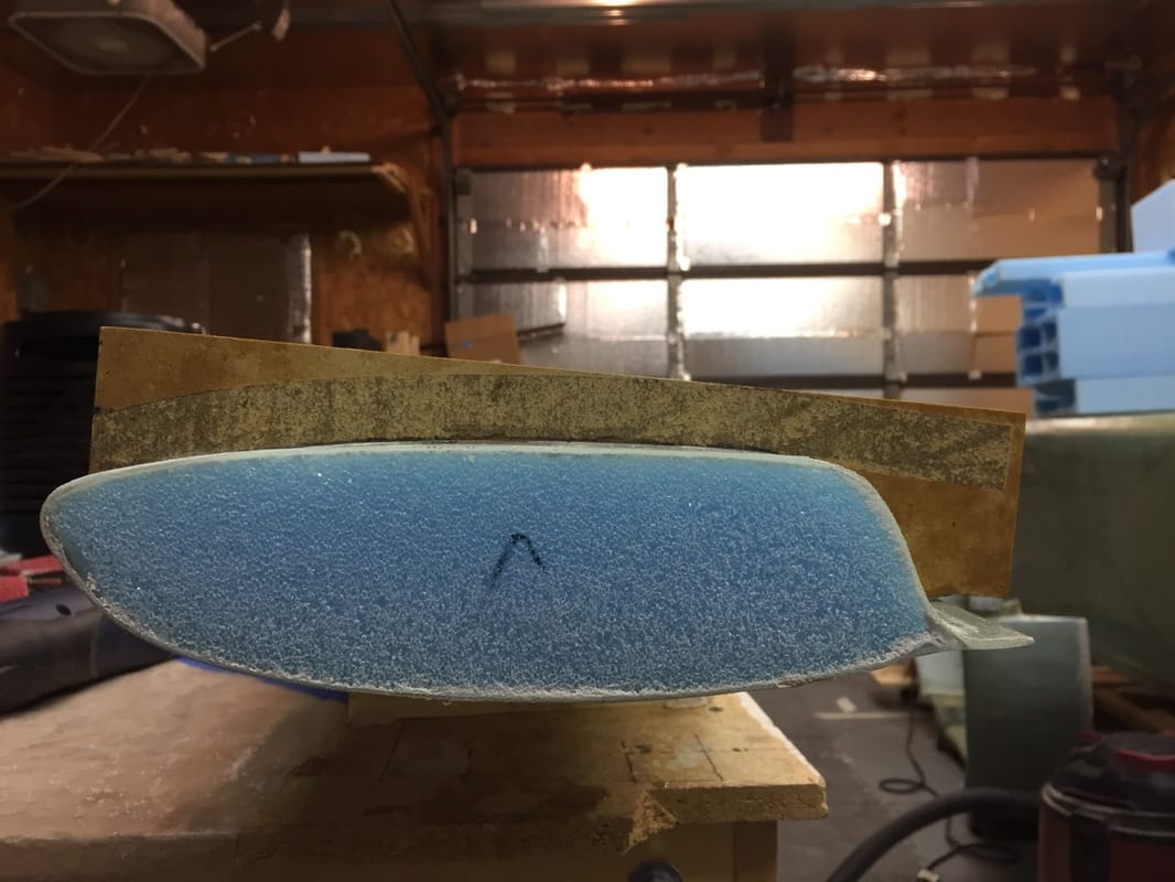
Well, disaster struck one more time. After removing the peel ply, and all the tape, my spar cap sat proud of the surface. In some places it was 0.03 - 0.04 inches above, others were 0.02 inches. I used 6 layers which according to the archives is about the minimum amount. After asking about it, it became obvious that most people were in the 7 - 8 layer range meaning I was well under. Likely cause is over rich layup that for some reason didn't remain at the foam surface. My fibers where straight, I was free of voids, so the only thing I could figure out that went wrong was not getting enough epoxy out of the layup between layers. There was lots of discussion about it (more than I meant to make, and so I decided that with it being questionable that it was best to start over. So I sawed up the core in pieces and kept one as a reminder. The cross section actually looked pretty good, just taller than it needed to be. I did notice that the micro used to hold the leading edge on was a bit thick. Must have been too dry, so I'll have to make that a bit wetter next time. A setback for sure, but will continue on.

I did the rebuild much in the same way as I did before. Steve at EurekaCNC was able to just send me the cores that I couldn't salvage and at a price lower than getting the raw foam blocks (such a great guy). As I did before, I checked, the cores against my templates before proceeding. In order to clamp them in the jigs, this time I used metal j-channel. It was almost as cheap and was much more stout at holding a straight line. The shear web went on much like last time with few problems. This time I cut the 9 ply BID pieces for the lift tab inserts to 1.5 inches wide instead of 1.7 inches. These fit much better with less problems. I also made sure to pay attention to the angle of the lift tab inserts so that I could match the M drawing angle better. One tab ended up slightly more level than the other, but this can be fixed later on. Almost caught back up.
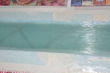
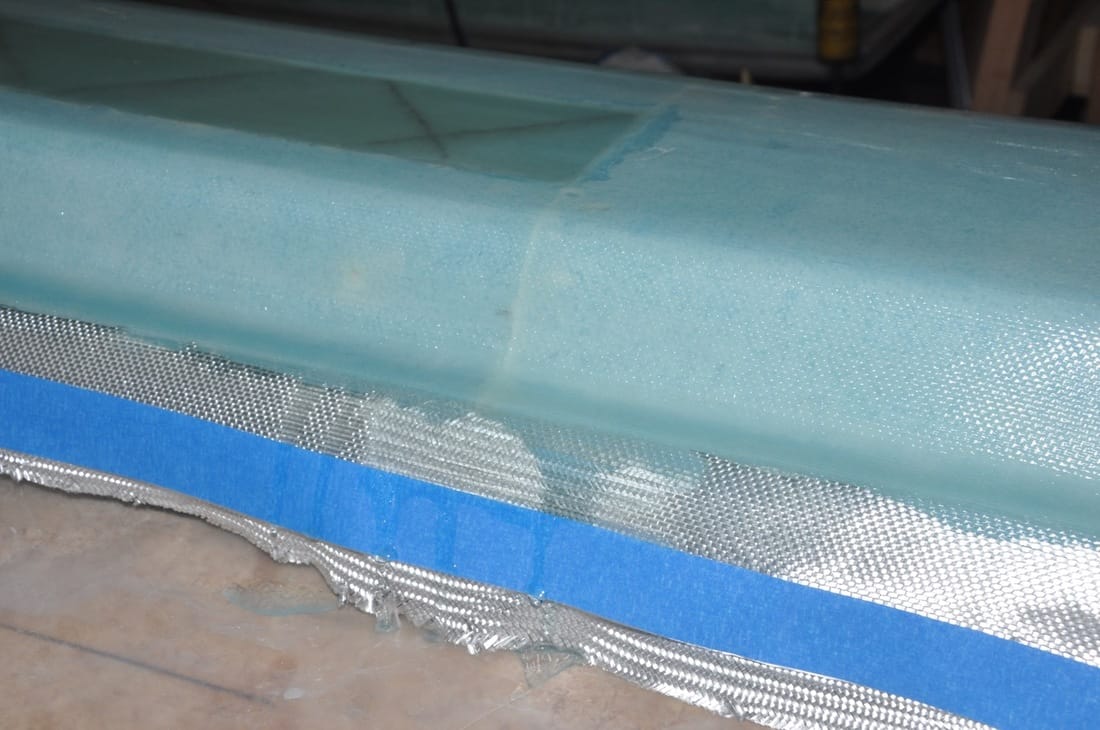
I decided this time that I was going to do both the spar cap and the skin layup, so I needed to have a second person to help out. This was because I couldn't stand the idea of sanding that spar material which created some of the worst itchy and pin pricking shards of glass I had dealt with. It would also make the best bond. So with the help of the wife, we laid up the spar cap making sure each layer was squeegeed as if it was the last layer (ie: get as much excess epoxy out). Just like before, it took 6 plies to fill the trough, but this time extra care was taken to ensure it was at or ever so slightly below the surface (to account for the tape). The first three layers only moved down by 2 inches each, then the last three changed by more. I did pretty much the same technique this time just with extra squeegee pressure. After laying up the spar, the tape and paper were removed, the 1 inch peel ply was added to the trailing edge and tacked in place with finishing nails, a piece of duct tape was added along the leading edge of the canard to protect the lower foam, and the foam surface microed. The first layer of skin glass is UNI full span. We pulled it tight and laid it down. I cut slits for the lift tabs, then made sure the fibers were straight as possible before wetting out. Next came the BID which is overlapped at the middle. Due the angle of the glass, a patch of the wing will not get covered in the back center area. Unfortunately, I placed this blank area towards the front and I couldn't remove the glass without great disruption to fix it, so I left it and added a small patch to the front. It's likely not needed and will add a bit of weight, but I wanted to be safe. This area is inside the fuselage so bumps don't matter much here. The pieces of BID on the ends only get butted up against the other BID layers. The last layer is another full span UNI. After wetting out all glass and doing a bubble and dry spot inspection, The glass was cut along the top of the duct tape and a piece of 2 inch peel ply was added to the front edge. I then did the plastic ply method on the top surface leaving the curved trailing edge area alone (was afraid the curve would cause issues with the plastic). The plastic smoothed out the weave and got even more epoxy out than the regular squeegeeing did as well as ensuring air was removed. This was left to cure.
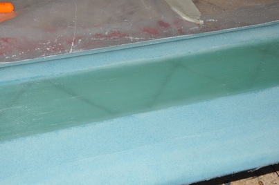
After cure, the plastic and the peel ply along the leading edge was removed. I left the trailing edge peel ply till I can cut the foam off to make it easier to remove. Others have tried to remove it and only pull out large chunks of foam, so waiting till the foam was removed should work better (time will tell). The layup looked really good! The area was void free except for one spot where the BID butted up against each other. Ironically, this area was under the peel ply, all plastic plied areas were void free. Hopefully the plastic ply effort will take less filler to fair in. After removing the peel ply and tape from the leading edge, I sanded and cleaned up the edge of the skin layup to assist with the layup of the top skin. Sanding the edge down will allow a nice transition of the new layers over the existing layers.
Last thing to do before starting to remove the canard from the jig was to trim and sand the trailing edge. The plans state that it's important to get it straight, so I tried my best to trim it almost to the foam edge then sanded it flush. Using 36 grit sand paper on a sanding block really helped to get a fairly straight line. Other than a couple of areas where my fein cut got a little too inside, it turned out very well. Hopefully I can fix up the couple of small goofs later when the top skin is done. We'll see.
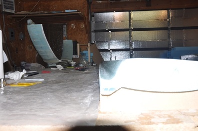
Next step is to mount a 1.25 inch diameter tube to the back end for support and install blocks with bondo to rest the canard on. I decided to go with the PVC pipe because my trailing edge was already straight. As long as the bondo adhered prior to removing the jigs, it should hold things in place okay. I took each board and made a notch in the back for the tube to clear, then I used stir sticks to level each board to the same angle. That way, when I turned it over it should sit flat. I mixed up bondo and attached everything. After cure, I used a utility knife to remove the cores from the jigs while trying to not damage the foam too much.
I then found what most others find out which is the peel ply is very hard to remove. The reason this happens is that epoxy seeps through when you're wetting the glass out and really soaks into the foam. I had originally tried to put a piece of tape over the foam to act as a barrier, but I had difficulty holding it in place. This would have helped a lot if I had been able to get it to stay and I would recommend it to another builder if they can figure out how to hold it there. My nail trick that I did use on the peel ply would have probably worked for the tape if I had thought about it fast enough. As it was, I had a heck of a time removing it. Found that if I could use the Fein to trim off as much of the epoxy-foam from the peel ply surface, then it would come up easier, but it was still a chore.
While checking the canard for twist and straight geometry, I noticed that one end of the canard had a small peak in the foam. It happened between the jig area where there was a long span with no jigs. Sometime during the glassing, this area sagged slightly, creating about a 1 degree change in incidence (as measured by a smart level). By this point the canard was pretty stiff, but you are suppose to have zero differences. So I made a couple of quick support boards with extra surface area, attached them to the table at the affected area, then mixed up bondo and packed the area while I placed a good amount of weight to push it back into alignment (the weight being myself carefully sitting on the canard). After a cure and rechecking, the bump was no longer visually present at low angle investigations. I had issues using the contour checker to verify the rest of the canard was good as I would get different readings on different days and the low level angle didn't show the differences it was displaying. They were all fairly small differences and could have been differences in the foam, so after inspecting things several times I decided it was best to move on.
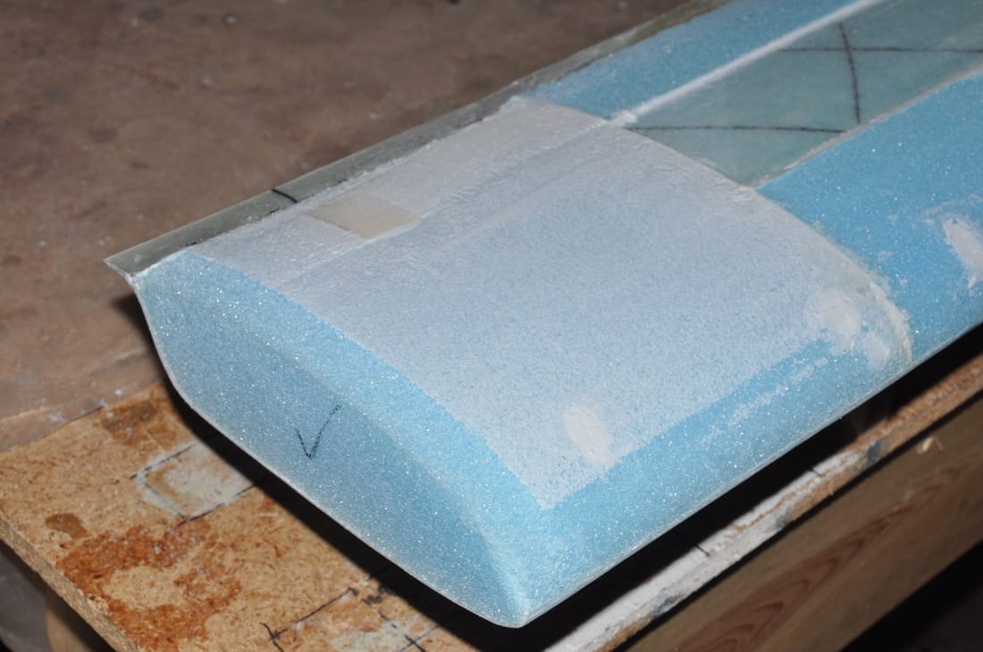
Next up was installing the high density PVC foam used for mounting the hinges. I had cut these previously when I had some down time using the M drawing as a template. I then marked the BL locations and verified their alignment with the actual cutouts in the elevator hardware. The book values were perfectly centered. I then marked out the cutouts. Warning, do ones of the ones along the trough area before you do the outboard points. You want to be about 0.25 inches behind the spar cap trough to start the cutout. The M-drawing was a bit deceiving on how to measure the placement. Just make the outboard points the same as the inboard ones. I used a utility knife to cut the outline, then cut out pieces from the area till it was cleared out. I test fitted then sanded the PVC foam till I had a perfect fit.
After getting all the foam pieces fitted, I mixed up micro and installed each piece filling in the gaps. I took time to level them as much as possible. I then went along and radiused the trough with micro just as before on the other side. I also went ahead and filled in the foam divits that were made removing the core from the jigs. I need to micro the outboard edge on one side due to the foam getting mounted slightly low to bring back into contour. I also sanded the outer edges of the canard to create the 1 inch wide depression to allow the tips to be glassed on. Otherwise, I'm about ready for the top spar and skin.
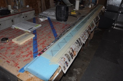
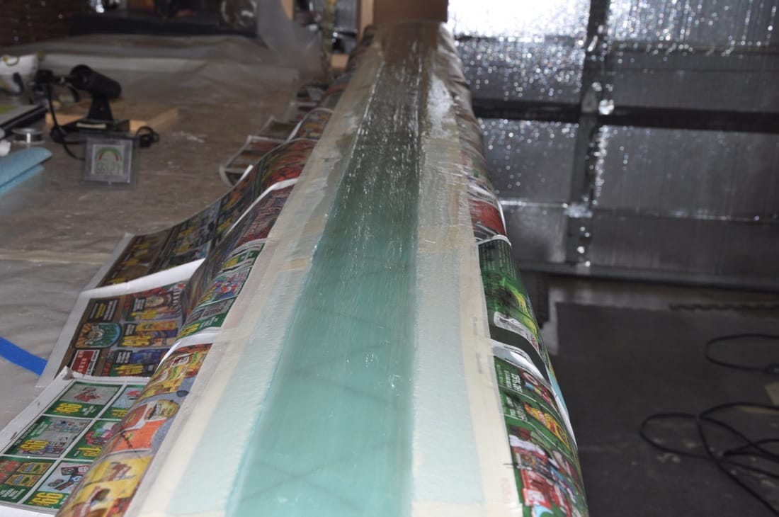
The top skin goes mostly like the bottom did with a few exceptions. First, the trough is deeper this time and will take a few more plies to fill. I will be doing this the same way as before using the template as a guide for how far to fill it. One thing to keep in mind is that the profile for the top will be more rounded while the bottom spar cap was flatter. To aid in getting this shape and avoid extra fill later on, I traced the profile from the template over the spar cap area and cut my plastic putty knife to shape. This will help me get closer (hopefully) the the correct shape. The other change is that there are four layers of glass on top. There will be 3 UNI and 1 BID layer this time. To prepare the surface for the layup, I made sure the foam along the trailing edge had enough radius to allow the glass to conform easily, I sanded both the trailing edge and the leading edge where the glass would lay over it, and I filled and contoured any spots that needed it in the foam and along the trough edge. Newspaper and masking tape were used to protect the foam surface. Knowing how long it took last time (about 7 hours, half that time with help), I planned a pretty full day for this and tried to get what help I could. Unfortunately, I was unable to get assistance so I tackled this on my own. Warning, this took me 15 hours, though I may not be the fasted worker.
I didn't change anything about the trough layup other than as I got close to the surface I used my modified spatula to shape the fibers into the semi-curved structure for better contour matching. I used 9 layers of UNI tape this time which was one layer more than the average reported on Cozybuilders and I suspect that was mostly due to trying to match the curved profile rather than remaining flat. This took longer than before but I think it was because the first several layers ran near full length unlike the bottom layers. The ends were cut at a 45 to avoid the sudden bump transition from one layer to another. Cross thread and key threads removed just as before.
Once the spar cap was done, I then removed all the tape and newspaper. After a final check on the contour with the surface of the foam, I proceeded to sand the trailing edge and the leading edge to ensure proper bond for the skin layups. I also decided to add a NAV antenna to the center of the canard. I had a freakout moment in the middle of it because the foil goes over the spar cap and you're suppose to leave it free to bond to the skin. I remember reading about adding a NAV antenna before skinning but couldn't find the reference. Other builders did the same thing and I justified that it probably wasn't a major issue since it was both in the middle of the canard where bending would be less and the tape runs across at an angle so there's bond with the spar cap all the way across. I couldn't see how one would get it positioned after one layer of glass anyway. To install, I dug out an area of foam at the middle, drilled a 1/4 inch hole, then made ramped transitions for the foil tape to RG-400 wire joint. The RG-400 was soldered to the foil after separating the shield and the center conductor. Three ferrite torroids were added as per RST instructions and the wire was passed through the canard through the bottom. The area was filled with micro afterwards and continuity checked. Hopefully I got it positioned correctly, but I may have to re-position it later on. Time will tell. There's no guarantee that I'll even use this antenna anyway.
For the skins, the top gets four layers: UNI, BID, UNI, and UNI. I was able to cut all three UNI from one length of glass and I didn't feel I was struggling to cover the cord of the wing. The first layer could have used slightly more and the last layer slightly less, but otherwise no issues. See the Tips at the top for how I did it. Due to not having help for this one, I had to lay the fabric out and then take extra time to stretch the fibers straight. Still, it took about 1 hour for each layer. The BID is done the same as before, cutting all selvege edges off and butting against each other on the outside edges and overlapping in the middle. I offset each layer by 0.5 inches which the plans tell you to do for the first two, but don't secifically point out what to do for the last two so I just continued the transition pattern. When the layup was done, I used 4 inch wide peel ply to smooth over the leading edge layers, though it was difficult to apply it upside down and by myself. The trailing edge and the edges of the canard were also peel plied. For the main surface, I did the plastic ply method getting even more epoxy out as well as some trapped air. This was left for at least 24 hours. After 12 hours of cure, I then bumped up the temp to better post cure the part before removing it from the jigs.
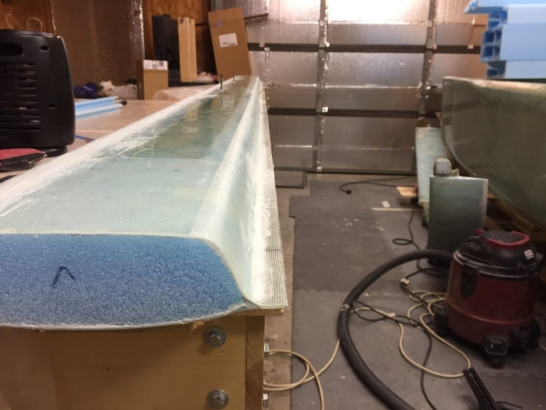
After cure, the peel ply and plastic were removed. The surface looked fantastic! Not perfect, but void free and no dry areas. The bottom of the leading edge didn't smooth out as much as I would have liked, so it'll need some sanding. Next step was to remove the jigs and sand off the bondo. I had to use a rubber mallet to apply side force to the jigs to pop then off. Removing the PVC pipe was a bit tricky, though removing the bondo from the curved surface was worse and just took awhile to do. Once all was done, the part was trimmed up, the leading edge bumps on the bottom sanded off, and the weight checked. I came in at 23.8 pounds. It's not the lightest, but it's also not the heaviest, so I can be okay with it. With that, I now have a completed wing! Time to add some moving parts to this beast!


|
Previous: Chapter 9: Landing Gear And Brake
|
Next: Chapter 11: Elevators
|
