Chapter 16: Control System
Now it's time to do some metal working, probably the most metal working there is in the plane. Timeline wise, I did this chapter after chapter 12. The reason was I could still put the fuselage on the rotisserie for easier access to working on the inside. This appears to be a well accepted plan of action for most people so I would encourage it. There are some changes to be made for the parts list for this chapter. I'll try to cover them in depth.
Special Tools Needed
- Drill guide for tubing (ACS #12-02937 or equivalent).
- #10 drill bit
- #12 drill bit or reamer
- 1.25 inch hole saw or wood bit
- 7/8 inch hole saw
- 1.5 inch hole saw (if using the bearing housing and bearing from CG Products)
- 1/4 inch drill bit and pilot bit
- Self-leveling laser line
- V-Block tubing drill guide
- Tubing cutter
- Deburring tool
- Files
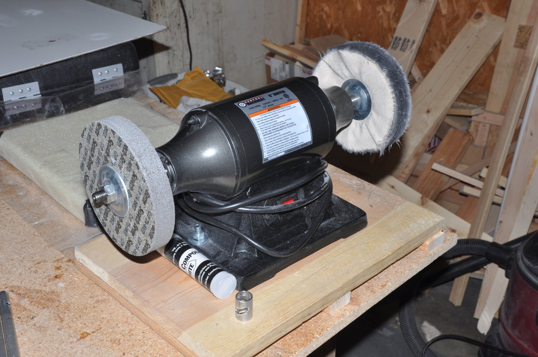
- Helpful to have: 3M - Scotch Brite Deburring Wheel C/P 7A-MED and wheel polisher
Tips And Hints
- Due to a change in the hardware, all the rod end bearings need to be updated to MM4 rod end bearings. This change should have been noted in the the plans updates from Marc's site.
- Note that because all the rod end bearings are now MM-4, every rod end threaded fitting will be a CS-50. If you go on the CG Products page, it will list that you need four of the CS1A. This is not the case and instead you need all CS50, 10 in total.
- The bearing blocks are easier to install when the fuselage can still be turned sideways. Therefore, this is good to do while the rotisserie can still be used. I skipped chapter 13 until I finished all the internal parts.
- The bellcranks from from CG products is made to plans which still have the AN-3 bolt sized hole. Drilling out to an AN-4 would make the metal too thin to support the weight. To get around this, you will need to order Aurora XM3 rod end bearings instead of the MM4.
- Replace the four bearings inside the fuselage with Igus EFIO-10 bearings (do not get the EFIO-10R as there have been issues with some being loose). These bearings are full plastic with low friction and will not corrode. The bolts will need to be replaced with AN-4 bolts to better fit the slots. Note that these bearings will work by the tube rotating inside the ball rather than the ball rotating in the housing.
- Do not cut tubing to the lengths specified in the plans, especially if you moved the seatback location. Better to test fit all parts
- If the plans roll trim will not be used, then an adjustable collar can be made for the piece of tubing that fits on the torque tube just forward of the control stick. This has a helical slot that allows for fine tuning the tension on the bearing to get no back and forth play in the assembly.
- If the holes in the wood blocks for the bearings are cut with a 1.25 inch hole and sanded to 1.26 inch, the Igus bearing housing will fit perfectly inside the hole and will not be able to move back and forth. The bolts will then be holding it in place and sliding forces will no longer be an issue since the bearing has slotted mounting holes.
- Mount the rear bearings in the wood bearing blocks as vertical as possible without the bearing block sticking up above the surface. This will allow thinning the width of the wood to make extra room in the plane later on as needed. The front ones could have issues with the pitch controls hitting the block and may need to be shaved.
- The plan's washers for the thrust loads at the stick portion of the bearing block are too big to fit within the Igus bearing assembly for the back side portion. To remedy this, make a 1/4 inch spacer from the same tubing as the torque tube in order to move the washer outside the bearing block assembly. It will still trap the ball from completely moving out of the assembly but allow free rotation of the torque tube.
- Handle the universal joints carefully as the orange flexible covering can dislodge from the housing easily.
- All connections to the torque tubes should be drilled and bolted vertically so that if the nut comes off the bolt will still be inside the hole.
- Use Zinc Phosphate primer to protect all the parts of the torque tube. make sure to mask the pivots for the control stick, the exposed part of CS-106 (part that is forward of the control stick), and most of the shaft for CS-121 (the paint won't fit through the bearings). If you get paint on anything that shouldn't have it, acetone removes it very easily.
- Hold off on drilling CS-121 till the wings are made and the aileron to stick positions can be better set.
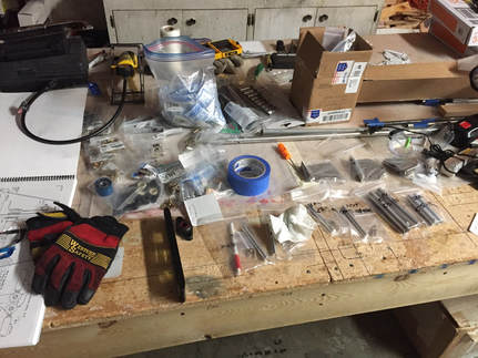
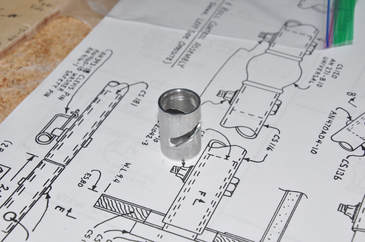
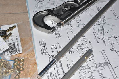
First part of this chamber is assembling the parts. There are a lot of parts involved here. I ordered most of my parts from the Cozy Girrrls as I'm not a machinist and they do fantastic work. There are also a lot of parts to order from your aircraft supply place of choice. I hope to make a list of the changes in materials soon. Yes, the shop is a bit messy right now. In between three projects.
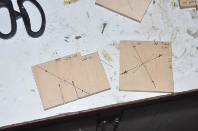
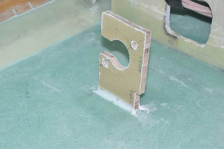
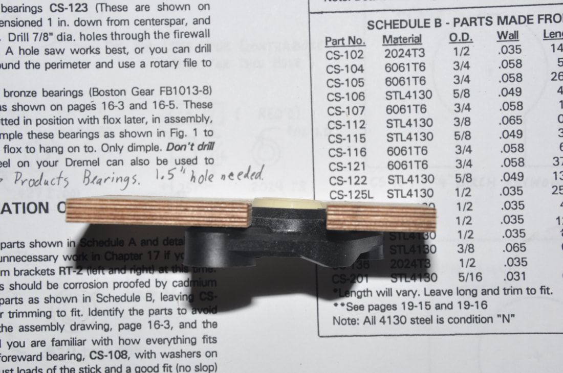
First thing I did was to make the wood bearing blocks CS-109 and CS-118. These are made from the same plywood as the firewall. I copied the outline of the part and the centerhole location for the torque tube onto tracing paper, then traced the image onto the wood. I marked the center location, then using one of my Igus bearings I found where it could be rotated to be as vertical as possible but not sticking out past the wood surface and marked this axis. The idea is that later on if I can remove some of the material to decrease the amount the armrest sticks out from the side, then I can so some space in the cockpit can be regained.
UPDATE!
So I may not have thought this through well enough. mounting the holes as vertical as possible is probably fine for the rear blocks, but it looks like I'm going to have fitment issues for the fronts. Once I got the controls to the elevators connected and was checking clearance, I'm hitting the lower portion of the block, which is common. I'll have to remove some material and I don't know if the bolts are going to be in the way. We'll see. For first time builders, I would leave the holes in the plans spot for the front blocks.
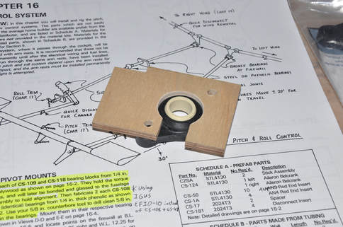
I used a 1.25 inch wood spade to cut the hole out for the Igus bearing. The top part of the bearing is 1.26 inches, so some careful sanding of the hole eventually led to a nice press fit of the bearing inside the hole. This has the advantage of removing any issue of the bearing housing sliding when the bolts are attached since the holes are slotted on the bearing. It also positions the bearing in the center. The holes for the bolts were drilled for 1/4 inch sizes to accommodate an AN-4 bolt.
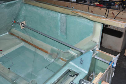
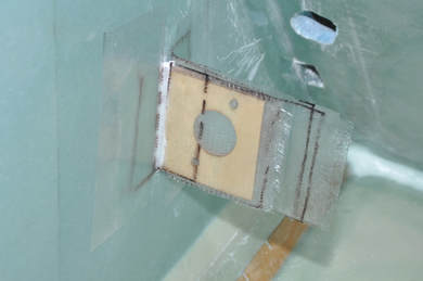
I had waited until this point to drill all the torque tube holes. In theory it would mean better alignment since things might not be in the right locations as you build. I didn't find drilling them now to be an issue, others have had different experiences. Before I did this, I first located the position of each bearing block keeping in mind that the upper longeron top surface is at WL 23. It took a bit to find the location of the back bearing blocks and involved measuring off the firewall and landing gear bulkheads. Once located, I marked the bottom and the edge location so that the part could be hot glued into place. I made sure the block was parallel with the bulkheads when gluing. This was easy to do by rotating the fuselage sideways so the glue surface was flat down and mounting the block vertically (verifying the bulkheads were also vertical). This will be very handy when the block is permanently attached.
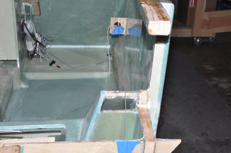
I added my tracing template to the block to show where the centerpoint was and marked the top and side of the block to locate the center without the template. Then I set the fuselage upright and level. I verified the location of the rear bearing hole and marked it. Using the laser level, I aligned this rear mark and the mark on the bearing block and made sure the line went across all the rear bulkheads. This marked the location of each hole from the side. Next I locked the laser line and positioned it so that it now went across the sides of the bulkheads, but again lining up the rear location and the bearing block. I had to drill a small 1/8" hole in the rear location so I could see it from the cabin side. This line located the hole for each bulkhead in the vertical direction. With both marks now available, the centerpoint was marked for each one.
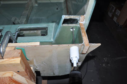
To start the drilling process, I first used my 12 inch long 1/4 inch drill bit. I started from the firewall drilling in line with my vertical marks and then drilled through the rear bulkhead. The front bulkhead is at an angle, but now that the drill bit is held by two other holes, the drill bit has some stability to stay in line. To start the hole, I carefully let the drill bit spin on the surface with very little pressure in order to not force the drill bit to bend. As the drill bit made it's hole, it reached a point here the last bulk head was holding the bit in place and pressure could be applied to finish the hole. When I was done, I looked through the back hole all the way to the bearing block. My passenger side holes were a bit high with reference to the bearing block. The pilot side were a straight shot to the center of the bearing block. Just means I'll have to adjust the passenger side some.
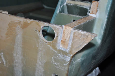
The holes for the bulkheads will take a couple of different bits, at least they will if you use a bearing for the firewall location rather than the bronze bushing. The bearing from CG Products requires a 1.5 inch hole. I bought a 1.5 inch hole saw from Ace hardware because these have been the only ones I can find that will allow any 1/4" bit to be used. I also got a 7/8 inch hole saw of the same type. What these type allow is to position them anywhere on the pilot bit, which is something that comes in handy. I cut this holes in a similar fashion as doing the original landing gear stud holes:
- Using a 1/4 inch pilot bit (round tube with no cutting surface), the 7/8 inch hole saw was positioned between the firewall and rear LG bulkhead and the pilot bit through all three holes. Cut half way through the bulkhead.
- Remove and reposition the 7/8 inch hole saw to the bottom of the pilot shaft (next to the drill head). Place the pilot through all three holes and drill halfway through the front LG bulkhead. Go slow till it's had a chance to cut into the slanted surface.
- Remove and attach the 1.5 inch hole saw at the very bottom of the pilot shaft. Cut all the way through the firewall with the pilot through all three holes.
- Reattach the 7/8 inch hole saw and position the pilot through the two remaining holes and finish drilling the front bulkhead from the front side.
- Finish drilling the rear LG bulkhead from the rear using the previous cut to guide the hole saw.
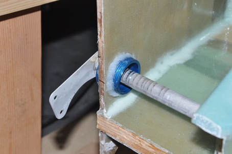
Next was to start trial fitting pieces. It was recommended not to cut tubes to the plans dimensions as changes may throw it off. First thing I did was take my pre-made CS-121 assembly (steel tube with aileron ears) and insert through the bearing from CG Products. Hint here, you want to mount it so that the flange on the bearing housing will be on the outside of the firewall side (not the cabin side). Otherwise you won't be able to remove it easily. I screwed up the first time. I chose not to flox this in at this time and will do so once the whole assembly is done for better alignment.

As an example of how life can get in the way, here's what happened to me during this chapter. My nine year old and I were heading to the store in the van to get supplies for my seven year old's birthday party. We were at an intersection with a light. Our light turned green, I cleared both directions, then proceeded to make a left turn. Another individual came through the intersection at 60+ mph (have not been able to determine the actual speed yet). The other vehicle impacted the side of the van by the engine luckily missing the doors. We were pushed 20 feet sideways due the stored energy of the other vehicle. We're both okay, but it did throw off our lives. Had to spend time dealing with insurance and finding a new vehicle, plus I still had to take care of the birthday party. So remember that things can happen, but to continue on.
In order to fit the control tubes all the way to the front, I needed to drill out the holes for the seat back. I did not do this when I made the seat. Whether this was better or not is hard to say. The actual drilling was easy. I just made a 1/4 inch pilot hole, then went slowly with a hole saw and presto! I was done with the hole. I did you a level made for bars to make sure the hole was level while drilling. However, the hole eventually will need some sanding to allow clearance. I used the CG Products front torque tube which is cut to plans length. I had moved my seatback 1 inch aft, so now the connection for the universal joint is just inside the seat. This required some sanding to allow the bolt and nut to clear the seat. Not a big deal but had to be done.
After a series of attaching and fitting and measuring, I eventually got all my tubes cut out. The method I used for cutting my tubing was the following:
- Using a tubing cutter, I cut through each tube by rotating the cutter and slowly turning the cutting wheel inward.
- After cutting, I used my debur tool to remove the edge on the inside of the tubing.
- If the outside needed some smoothing, I used emory cloth.
- When I'm ready to alodine the parts, I'll do a final polish on a polishing wheel to remove all scratches and nicks.
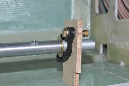
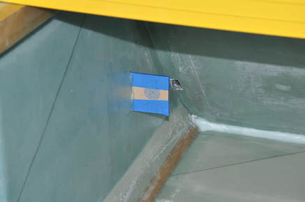
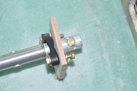
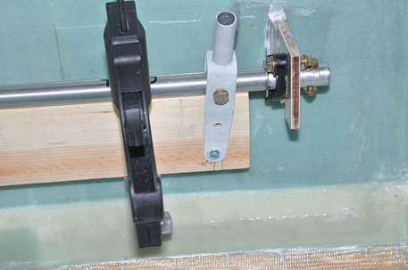
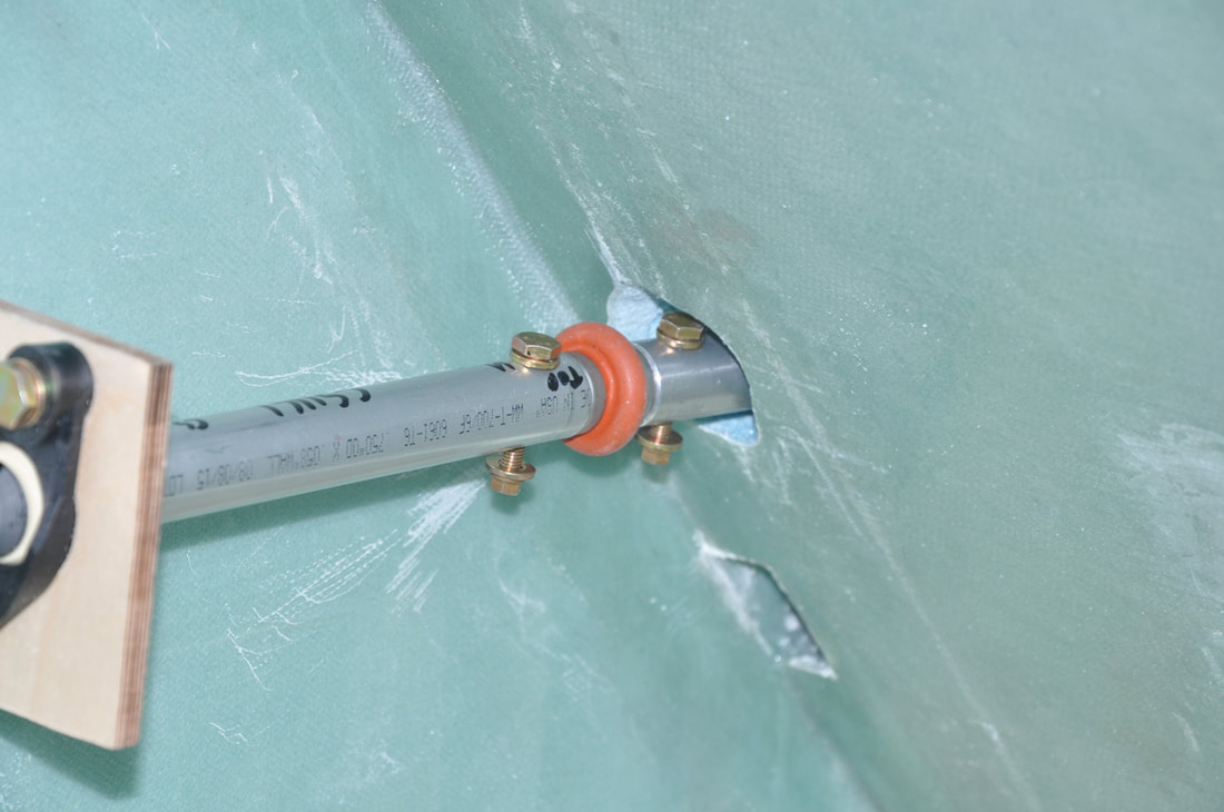
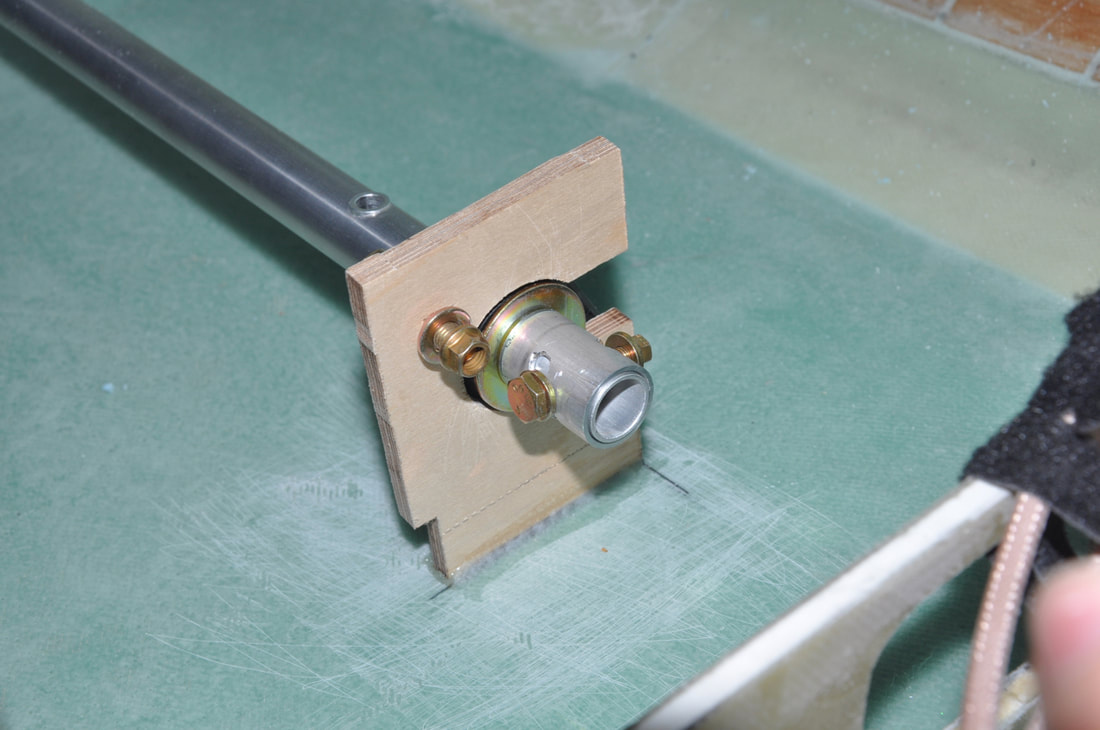
During the trial fit, I realized there was an issue with the plans thrust washer on the aft side of the front bearing. The Igus bearing has a dished backside which causes the washer to hit the housing rather than rest on the face of the ball. This does not take up the thrust loads and causes friction in the control system. The solution was to cut a 1/4 inch spacer from the torque tube tubing. The piece was deburred, then I added the washer, followed by the spacer, then inserted this into the Igus bearing. You can see the spacer between the washer and the bearing housing in the image. While it does leave a bit of a gap between it and the housing, the ball is still captured in case it pops out. I don't believe the thrust loads are high on this assembly, so this should be okay.
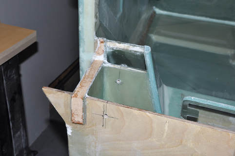
Once happy with all the tubing fittings, I floxed the two bearing blocks into place. For the front block, I needed to move it 1/4 inch forward to make up for the 1/4 inch spacer so the stick would remain in the correct spot. Don't know if this was necessary, but it was easy enough to do and may avoid some fitment issues later on (like fitting the torque to the elevators). Eventually, these will get glassed over later in this chapter. I used some small levels and tape measures to make sure the blocks were parallel with the IP bulkhead. I did use the 5 min epoxy dabs to help grip them while the flox cured.
Once I was happy with the fittings, it was time to start drilling holes. I'm holding off on drilling the hole through CS-121 as recommended by a few as it will be easier to adjust the position when the ailerons are available. I might change my mind, but we'll see. The idea is that it's hard to tell where to set the stick tilt at this point until you have ailerons to check. The method I used for drilling the holes in an attempt to get non-burred holes was the following:
IMPORTANT!!
Make sure to mark both sides of each tubing and make a top hole reference mark as well. For example, the image has the CS-116R piece (right side). I marked the top holes and marked the name of the piece that matching on each side. This will allow the tubing to fit together without frustrations later.
- Verify the drill bit is centered on the tubing. This can be done by taking a flat razor blade, placing it on the tubing, then press the drill bit down on the surface. The razor will be flat when centered. I used a level to verify.
- Drill with a small bit first, I used 7/64 inch.
- Drill with an intermediate size, about 11/64 inch.
- Drill with a #13 bit.
- Finish with a #12 reamer for a close tolerance hole.
IMPORTANT!!
Make sure to mark both sides of each tubing and make a top hole reference mark as well. For example, the image has the CS-116R piece (right side). I marked the top holes and marked the name of the piece that matching on each side. This will allow the tubing to fit together without frustrations later.
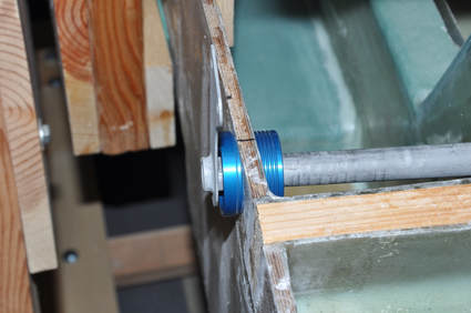
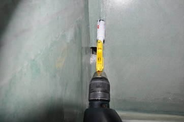
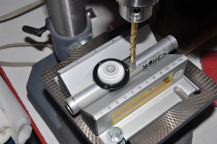
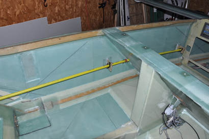
I got to meet Joe Person at Kanab in 2017 and talked to him about his adjustable locking collar. He had recently posted about it on the forums. The idea was to replace the tubing piece for the plans roll trim (which I wasn't going to use) and make a spiral slot which allowed the tube to be turned to fine tune the locking point. That way you can dial in the right amount of tension rather than having one shot at it and hoping you can take up the rest with washers. You have to decide how much adjustment you want when making the slot. A slot closer to perpendicular with the tubing will give a lot of fine adjustment. A slot more parallel with the tubing will give more adjustment but make it harder to do fine adjustments. I decided to go somewhere in the middle but more towards the fine. I used a laser line to get a straight line across the tubing and marked the beginning and end points and points along the middle. Then I drilled out a series of holes followed up by using a file to smooth out the opening. Use a drill bit smaller than the bolt (small than a #12 for AN-3 bolts) so that when you file it open the hole won't be too big. I'm not a machinist, but I did as well as I could. It functions even if it's not the prettiest.
I drilled the hole for the adjustment collar so that it would fall in about the middle of the adjustment range to give me the most options. This adjustment will allow the tension to be set just right (take up slack but not make the controls too tight). This allowed my trial fits to work very well and seemed well worth doing it.
Something I thought I would put in here is that I decided it was time to trim the LWY excess. I don't remember seeing any instructions about this prior to this point, but since I now had the ears from CS-121 in place, I needed to remove them for clearances. I just used the fein tool with my HSS flat blade cutter to remove these flush with the surface.
With everything else bolted up, I went ahead and floxed the bearing in the firewall while all the tubing was fitted together. This allows everything to keep the proper alignment while the flox cures.
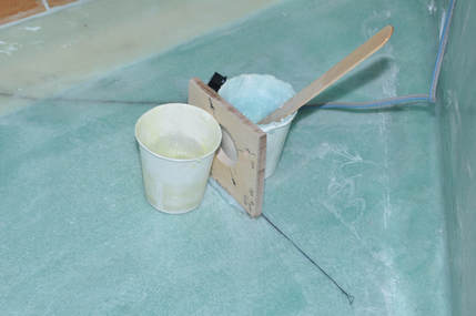
With the controls figured out, I removed all the tubing and bearings and prepared the bearing blocks for glassing. First, I removed any flox bits that were creating bumps in the surfaces. Next, I made templates on plastic to cut the fabric to shape with a small amount of overlap. I also drew the transition line to allow easier placement of the layup along the corner. I left excess (about 0.25 inch) around the bearing block to ensure full coverage and give some to trim back to a perfect fit. I decided to not cut the holes out as that seemed like it would create more problems than solving. 2 ply BID was laid up on both sides of each block using Micro to radius the corner. I used plastic ply to smooth out the faces and the overlap on the fuselage sides. This was left to cure before trimming.
To trim, I just used the fein cutter to trim off the excess close to flush then sanded the rest of the way. To cut out the bearing openings, I used the same circle bit and marked the middle and just carefully cut out the circles. One hole I accidentally used a larger size up (not much larger, but enough. I didn't notice due to the angle I had to cut at and ended up shaving wood away. I filled this with flox, cured, then reshaped to the original opening size. Oh well... I also redrilled out the bolt holes for the bearings and deburred the holes.
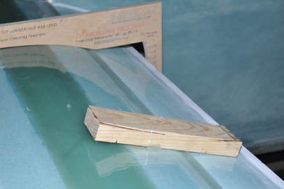
At this point, I reassembled the torque tubes as well as adding the stick grips to the assembly. The canard was then reattached. Now starts the process of connecting the canard elevators to the stick. First I had to lock the elevators at 0 degrees. I used the elevator template to locate the correct spot, then I used a block of wood and hot glue to glue it onto the elevator and the canard. This locked it into position. I used a small amount of glue to allow for easier removal later.
Next I needed to lock the control stick at a 5 degree forward slant. To do this, I borrowed a tip from Wayne Hicks and took a 3/4 inch thick pine board and marked both a 90 degree angle and an 85 degree angle both originating at the top in the same spot. I placed the board in between both legs of the control stick, positioned it so that the 85 degree line was centered through both holes on the legs of the stick, then clamped the board in place. I used a small screw and washer to help secure the stick into position.
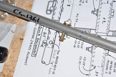
I decided that cutting CS-102 to the specified 14 inches made sense as I could adjust CS-136 which is the shorter part that connects to the elevators. The tubing was all cut using a standard tubing cutter. Once cut, the ends were sanded to remove the rough materials and the inside deburred. I added one CS-50 to one end, marked the location of the bottom of the insert, then drilled two 1/8 inch holes at 90 degrees to each other with just enough separation for the rivets to be installed. Using my squeezer, I was able to set the rivets nice and quick. These will hold CS-50 in place. I also added on CS-108 which is a solid aluminum rod that is used for the quick disconnects for the canard. This piece is permanently attached to CS-102 by two rivets. One thing I found was that the drawing in the plane showed a written value that indicated 2.1 inches went on the rivet side of the connection, but the drawing itself showed the 2.1 inch length on the removable side. It made more sense from the perspective of keeping the removable connection more fitted, so I followed the drawing and put the shorter end on CS-102. Again, this was riveted in place with two rivets at 90 degrees to each other. I did have to use a file to remove some material inside CS-102 in order to get the rod to fit. This is from the tubing cutter pushing in on the tubing.
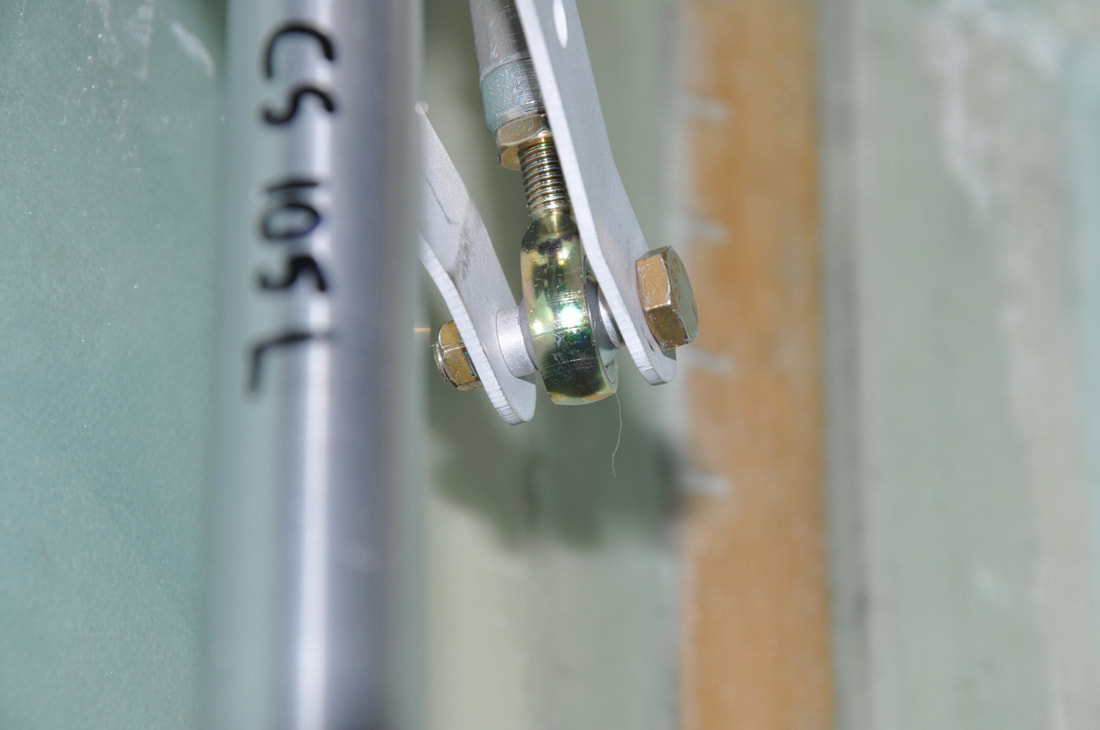
When it came time to cutting CS-136, I went ahead and attached the rod end bearing insert to one end and added the MM-4 rod end bearings. I turned these in till they were half way threaded, which appears to be the standard protocol for installation. I then fitted them up and marked where I needed to cut to get the correct spacing. After cutting, filing, and fitting on the quick disconnect, the length was rechecked. Once all was good, I went ahead and drill a single #13 hole through CS-136 and CS-108 followed by reaming with a #12 reamer going the opposite direction. This was to allow the use of an AN-3 bolt rather than a clevis pin for better security. I made sure the hole was drilled so the bolt would be vertically oriented as is standard aircraft practice. I was happy to find out that I needed the same lengths for both sides, so something went right for a change. For the record, my total distance was 25 inches from hole to hole.
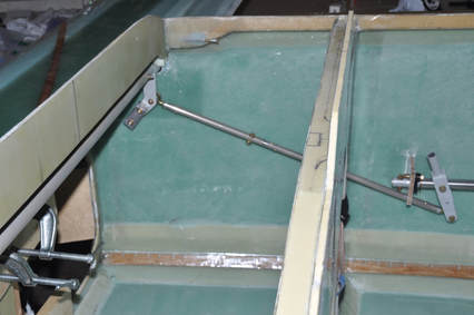
With everything cut and assembled, it was time to connect the elevator! First, I adjusted the assembly till it was the correct length, then locked the lock nuts for the rod end bearings. Next, I removed the pine board. Then, using the CS-201 spacers and a wide area washer, I assembled the top connection as specified in the plans. This gets attached on the outside part of the elevator spools between the spool and the fuselage sides. I had an issue with getting the bolt to fit on the right side which is probably due to my mistake with F28. It just means that I'll have to have the parts on the elevator before I install the canard in the fuselage in the future. For now I just used a shorter bolt to check the fitment. I also attached the bottom part of the connection to the stick. The sticks are now locked in place. When I removed my glued block, I could move the elevators up and down with the stick! A new moving part is always exciting. I can tell that I'm going to have to remove part of the bearing block bottom to avoid control interference.
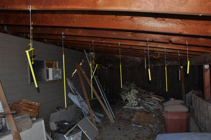
Now that everything was connected and fitted, I disassembled the entire controls and prepped them for corrosion protection. First I cleaned off the outside of any oils that might have been on the surface and allowed the parts to dry. I then used string to hold the part up for painting and drying. The parts were taken outside to paint which I was using a spray can style of primer from Aircraft Spruce. The choices were yellow or green. Green seems to be the popular one but I decided to go with yellow hoping that it would show up issues better and it made one of my daughters happy (her favorite color). I left the tubes to dry for several days as this material is slow to fully cure. Plus it made for a nice art decoration. One nice thing was that I could still see my writing under the paint, so my part identification was not only visible but protected.
After cure, I reassembled all the parts. I had to remove the primer from CS-121 and CS-106 due to tight fitment issues. This was easy to do with acetone. The yellow sure made everything brighter. At this point, I can't do too much more with the controls because I need the wings and spar made before I drill CS-121 to make the alignment easier. I'm also holding off on rudder cable runs because of a potential change that will eliminate the pulleys on the firewall, that will get documented somewhere, potentially Chapter 15. In my timeline, I then moved to Chapter 24 while it is still easy to work inside the fuselage.


|
Previous: Chapter 12: Elevators
|
