Chapter 5: Sides
This chapter marks the first movement into the world of curves for this project. It's also the first of the large layups (outside glassing and wings being the others). The things involved in this chapter are creating the wooden jigs that will be used for making the upper longerons and then used to form the curves that will define the shape of the sides. Spacer foam is added to shape the sides up and create the electrical channels. It is finished up by attaching the longerons and the wooden stringers for the landing gear then trimming to fit. Lots of fun in this one!
Tips and Hints
- PVC foam doesn't seem to like dry micro spread on it too much. When prepping the surface for a glass layup, use micro that still has a small amount of flow to it to avoid bubble issues during cure.
- Make sure to set the wood doubler for F28 at the 6.25 inch mark from the front rather than the 5.9 inch mark.
- When making multiple jigs of the same shape, make one perfect, then trace it out onto another or use tools that will cut one to the same as the other (example: flush trim bit on a router).
- Round all the wooden edges on the upper longerons where the glass must go around to allow the glass to lay down better.
- When securing the masonite to the wooden forms, make sure to only nail down the corner that touches. The masonite will not sit flush on the wooden forms and will only contact on one side. By securing only on that corner, your side will retain the proper curve.
- Apply mailing tape to the edges of the masonite to avoid epoxy attaching to the jig during layups.
- A router makes cutting foam reliefs very easy and quick. I used a 1/8 inch flute bit to route out the fuel sight gauge areas.
- When making the spacers, if you want to round off the corner where the tape stops and the flat top begins, make sure to oversize the flat area or the longeron will have a gap when installed.
- When doing the large layup over the foam, make sure that the micro layer isn't too thin and spread the epoxy out soon after mixing. Also make sure the temperature in the room stays above 70 degrees F. This is the layup where lots of people have gotten many bubbles under the surface (me included).
- 3/4 inch thick wood will work fine for the spacers between the sides rather than the 7/8 inch spacers.
First order of business is to create the FJ-forms that will be used throughout this chapter. Most are either straightforward triangles or rectangular pieces. There is one form, however, that has a curved side: FJA. The plans shows the overall length then gives various measurements along it's length for the height. I just drew markers for these heights then smoothly combined the points by hand. More than one piece is needed, so after rough cutting the pieces out of flat pine board each one was clamped to the original and a flush trim router bit was used to cut them to the same profile. Each part was labeled for easy referencing when using them for the different builds.
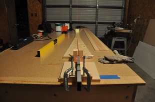
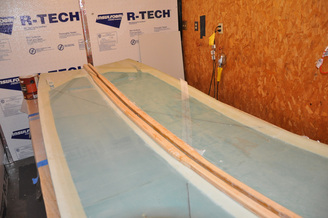
Here's the first time where the full length of the table will be used. The jigs are too long to fit on 8 feet (they are nearly 9 feet so some would hang off). So the two tables were leveled as much as possible, to surface covered with plastic, then a laser was used to reference a straight line that the jigs were attached to. The jigs are placed flat on the table to make the longerons with and the ends are both separated by 1/2 and inch. This has to do with the curve of the longeron taking a tighter turn than the sides will since it sits within the curve. The jigs were screwed down to the table top with drywall screws to keep it flat and from moving. Mailing tape was added to the edges of the jig to prevent sticking to the parts. Everything was rechecked for proper measurements before proceeding.
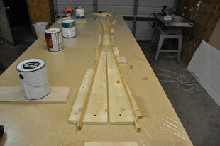
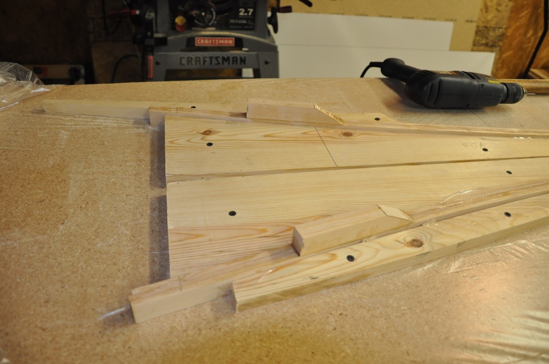
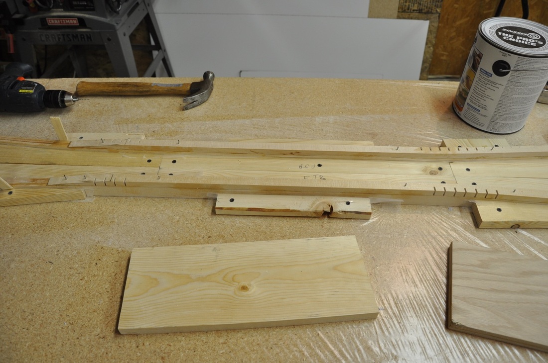
The longerons are made up of several wooden pieces. Each one is made of three long pieces of 1.5 x 0.3 inch spruce, an aft doubler, a central doubler, and a forward doubler. The doublers were all made to plan except the forward doubler. I made this one slightly longer due to reading about the trials of getting this piece in the right spot (I think I over-worried about it). The issue is that if you follow the plans marking of putting this at 5.9" from the front there will be fitment issues with the canard later on. The consensus is to place it at 6.25" from the front. I did this, but also made the piece slightly longer than needed in case I messed up somewhere and would hopefully be okay. Now that it makes more sense, I might go back and shorten the other side (the slanted side) to be where it should have been. Main thing is to place the forward facing part 6.25" from the front end and you'll be fine. When making the middle doubler you need to pay attention to which side you put your relief cuts. You should have two pieces that are mirror opposites of each other, or it'll cause issues later on. I just used the table saw to make the angled cuts and relief cuts for all pieces. Afterwards, these get epoxy applied to the surface then clamped into place in the jig. For the middle doubler, finishing nails were used to help hold it in place to keep the proper alignment with the other wood. This worked well and left a very small hole. Weights were added with plastic release material in between to keep things from sticking.

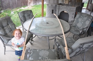
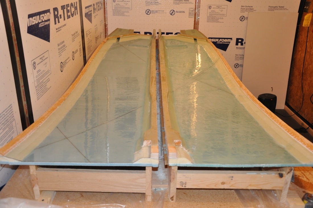
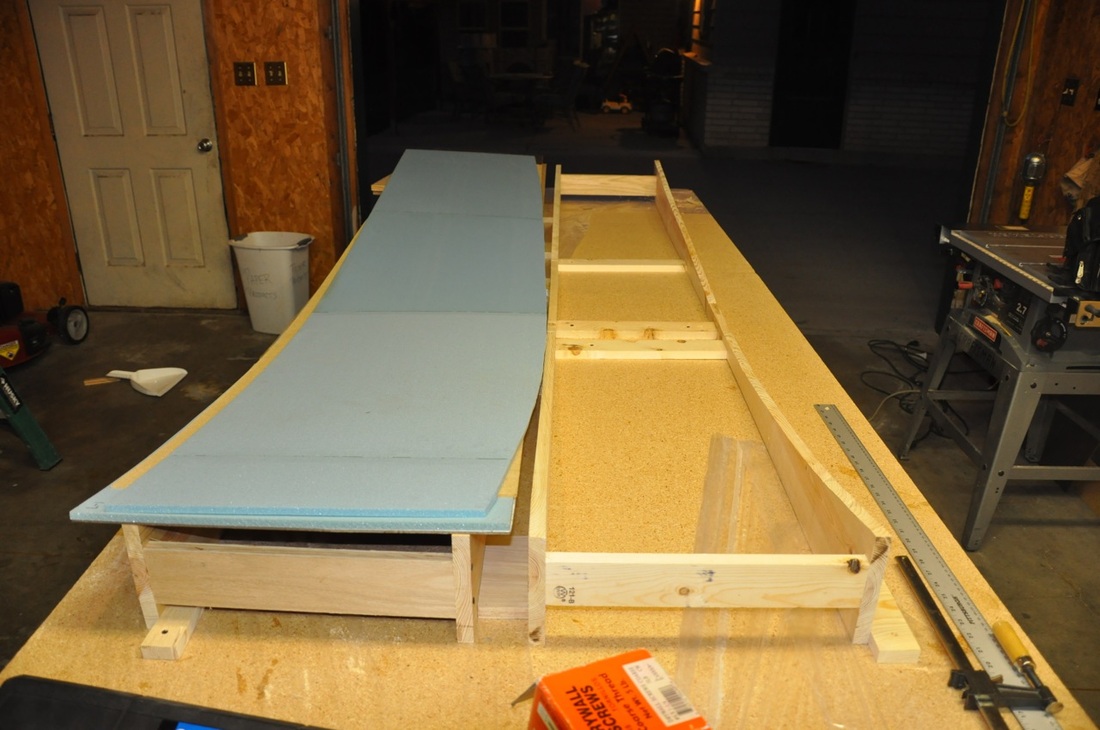
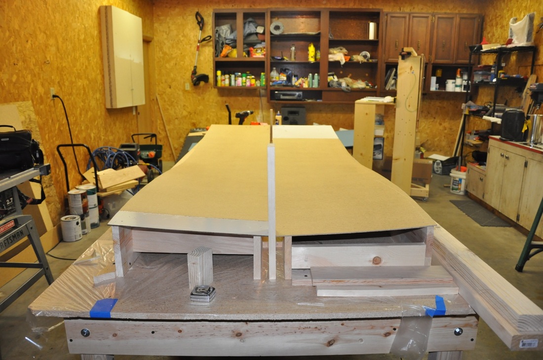
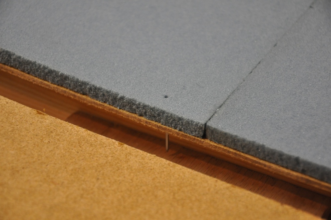
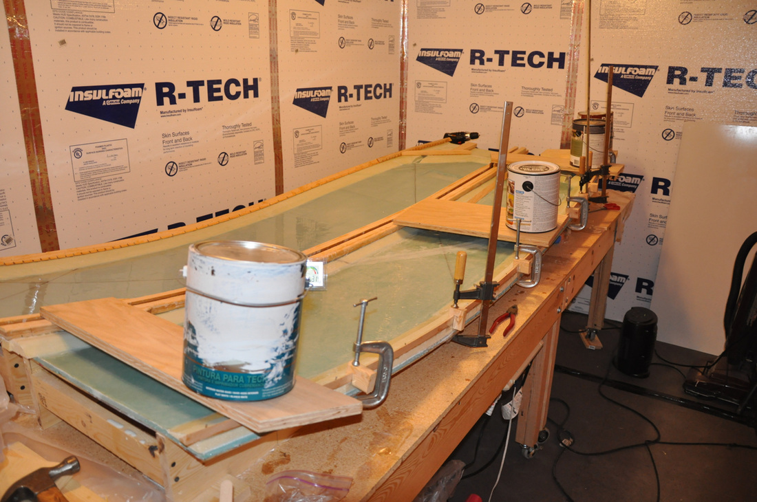
Once cured, the longerons were removed from the forms and inspected. They looked pretty good. Inara in quality control gives her approval. After this, the jigs are unscrewed from the table. The masonite was laid out with the extra inches needed glued to the end with 5 min epoxy (hinge method). The dimensions for the sides were traced onto the masonite and them the pattern was cut out to form the support jig and create a template for the foam. The foam was laid out on the table and the masonite was laid on top to trace out the cut. Once traced, the foam was cut out and the pieces glued together with 5 min epoxy (hinge method). The jigs (J-forms) were turned 90 degrees to orient the curve upward. Cross spacers were made and attached to help hold the jigs vertical and retain the correct width. They were also screwed down to the table to avoid movement and to make sure they remained in proper shape. After that the masonite was added to the top, aligned according to plans, then finishing nails were driven on the edges that touched the J-forms. Wayne Hicks has a good explanation of this, but you can also see it in the pictures here. The foam was added on top, aligned, then secured in place with finishing nails by driving them slightly below the foam surface. The reason I used the nails was that I could drive them through the masonite fairly easy, they leave a very small hole to repair, and when done you can lift the piece straight up without having to remove them. They held the foam in place very well. One thing I neglected to do was add tape to the edges of the masonite. This made remove difficult later, so I suggest adding it.


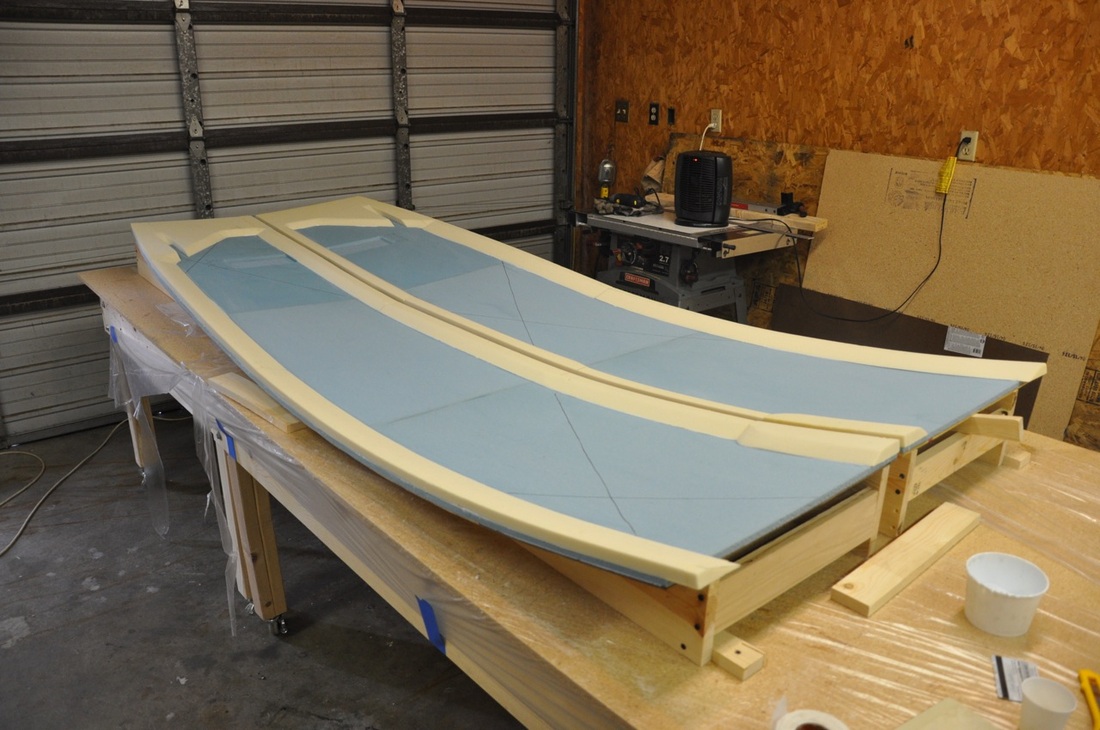
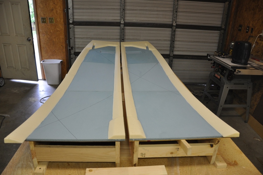
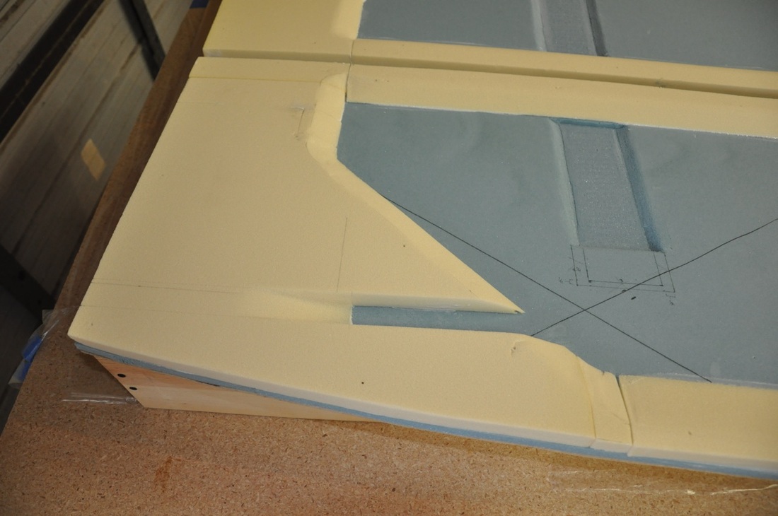
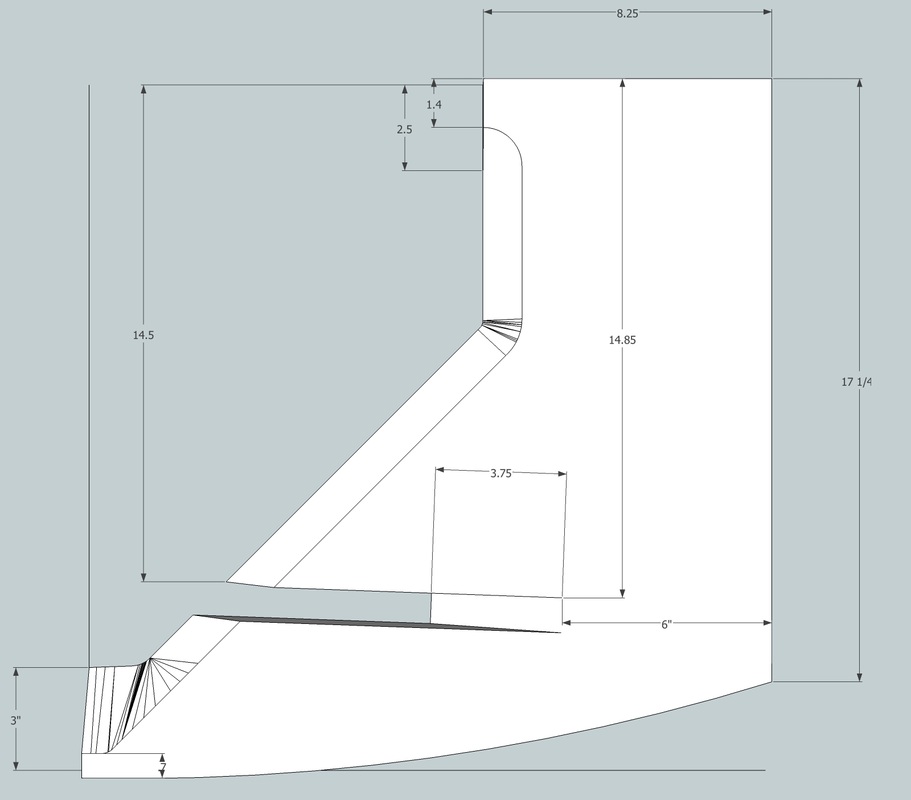
Next order of business is to make the foam spacers to help give the thing some shape. The plans does a good job of showing the shape of the spacers, but leaves the back area with some lack of details. After going over other sites and calculating out, I made a model of this area in Google Sketchup (mostly because I don't have a CAD program at home, and this is readily available). I made a jpeg with as many measurements as I could do. Hope this is helpful to someone. If you would like my original Sketchup file, it's downloadable under the images. I followed the recommendation of using the three inch slope to ease the transition of running wires through the electrical conduit. To glue the foam down, you need to spread micro slurry on both sides of the foam, then place a good sized bead of micro in the center of the bonding area and press down with weights. If the slurry isn't added, the micro is harder to spread out and may not evenly distribute. Scrape the excess away and use finishing nails to help hold in place.
| spacer.skp |
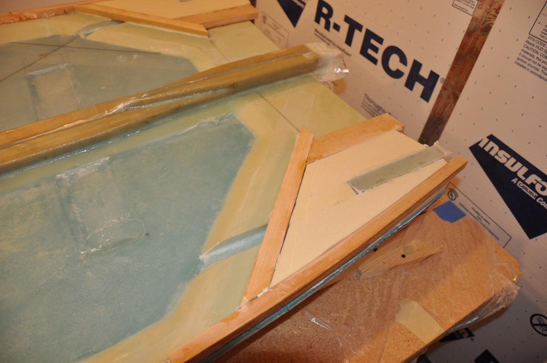
Once the spacers cured, the nails are removed, the final preparations can be done for the "big layup." At this point the reliefs for the fuel sight gauges were made. I chose to make mine to within 1/4 inches of the foam bottom. This left enough foam to glass to, recesses the gauge so it won't stick out as much, and leaves a small amount of foam to deal with when the time comes to make the glass-to-glass transition. Anticipating having issues lining things up, I routed the area longer than needed vertically in order to be able to set the gauge exactly at the bottom of the tank when the strakes are added. The rest of the area will be filled in with Micro once positioned. The relief was cut out by marking the outline then using a router with a 1/8 inch flute bit to cut out the foam. The router was set to stop at 1/4" above the masonite in order to leave 1/4 inch of foam. It makes for a quick relief of the foam and leaves a clean surface to glass to. I angled the edges of the relief to 45 degrees to make the glass easier to apply later. This was done by taking the fein tool and cutting at a 45 degree angle and finished off the edges with some light sanding. This would also be the time to make the stick reliefs for the control stick, but since I plan on having extended strakes, I don't know if they will be necessary, so I decided to leave them out for the time being. It won't be that much hard to do them later since you have to cut out the side anyway.
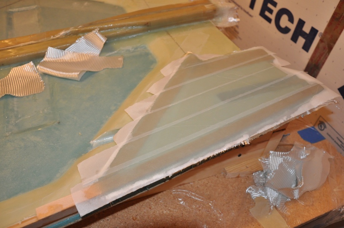
So here comes the big one. It's now time to do the first large layup: 2 ply UNI across both sides, then attach the upper longerons. Plan for 6-8 hours even with help (help is highly recommended). The entire area was vacuumed off to remove all dust and debris. The glass was precut and rolled up ready to go. All that was left was to glass it over. So micro was spread out over the foam surface as before, then the first layer of glass layed out and wetted, then the second layer layed out the opposite direction as shown in the plans, then peel ply added to the bottom, around the landing gear bulkhead area, and along the upper longeron area for future layups. Plastic was layed out on part of the piece, but the epoxy was setting and it had to be abandoned in order to finish the project. This just means that the area not under plastic will still have the weave visible and it won't be as light (in theory). Better than losing time fighting with it. After all that, the upper longerons were floxed in place and held tight with clamps and weights. Last bubble check and it was left to cure. Simple, right?
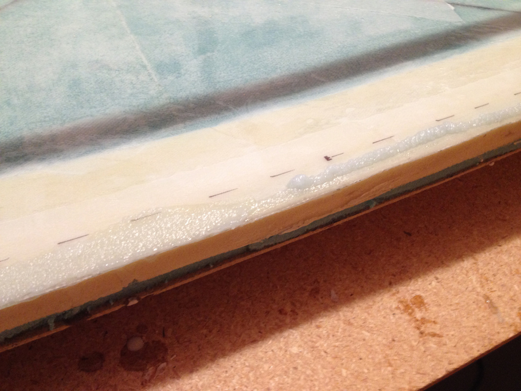
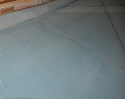 Small voids underneath the layup.
Well, you can have the best of intentions, but things still happen. One side turned out fine, but the other was riddled with small air bubbles all over the piece. After talking with other builders and thinking about things, the cause appears to be a few things: the micro spread out on the foam might have been too thin (overly scraped off to make the coat even) and the temperature may have dropped too much. This layup was done on essentially the last warm day of the year. I had a heater on standby and we were running it, but it wasn't keeping up with the plummeting temperatures. The combination of the two seems to be the catalyst. Apparently, the blue PVC foams is notorious for this, so I would suggest keeping the micro a bit thicker on the surface of this foam for this reason. The bubbles were well past the 10% allowance plus I couldn't feel good about it, so the decision to redo was made. There was nothing left to do but cut the upper longeron free and rebuild the piece. It wasn't worth trying to remove the glass for the amount of foam there was. One thing you learn though is how well that longeron was glued in place. Flox is hard stuff. I will say that this exercise does give you an idea of how well your work is going by how hard it is to remove things.
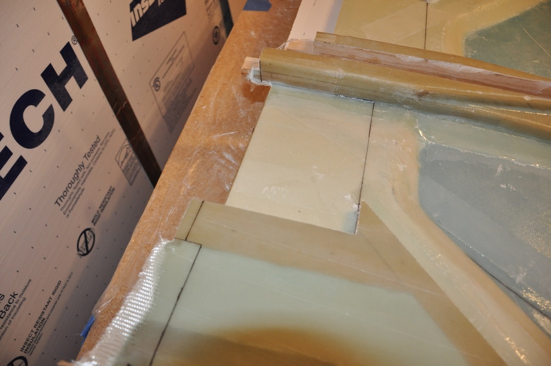
 Both sides caught up.
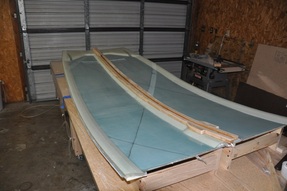
Once the longeron was freed, new foam was ordered and cut back into shape. This was the point of my first big slowdown while I figured out how to keep a warm room. See Chapter 3 for the details. Once back in action, the new foam side was caught up and glassed out. Using info from the forum, I spread the micro on thicker as scraping too thin could cause an issue. So I spread it out as evenly as possible, but didn't try to scrape too hard to remove the excess. I think the idea is to have enough to fill in the gaps, but also have some excess epoxy so it doesn't get soaked up by the glass and create voids. The surface doesn't have as uniform of a color as the other, but if it means less air it should be fine. It was at this point I learned the trick to getting glass well wetted out in good time is to dump your batch of epoxy right after mixing and spread it out everywhere you can. It will be at it's thinnest when just mixed so it'll absorb in on it's own. I ended up with some small dry spots in one area but another area was fully wetted out. They only difference was that I had spread the epoxy sooner on the good area. UNI is harder to wet out, so take all the help you can get. Once cured, the plastic and peel ply were removed and the piece inspected. Not quite as perfect as I would like, but still passes all the criteria. The electrical channel area and the edges were trimmed. Onward!
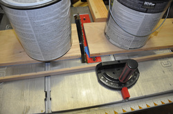
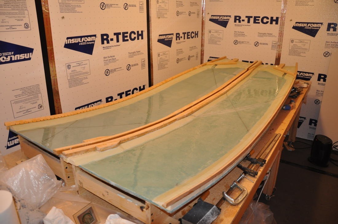
With both sides caught up, I was able to move on to new stuff (such a nice feeling after a couple of months). The lower longerons were prepared by notching the wood every 2 inches along the entire length and every 1 inch at the high bend points. This is half the lengths given in the plans, but as many builders have found the wood can be a bit difficult to bend into place due to the compound curves. To notch the wood, I drew notch lines were I needed them then set up the table saw to stop the wood at the 0.4 inch mark (slightly less than the plans allowed length) and just went down the line notching the wood. This went quickly and make for an accurate cut. The fitment was checked to be sure that the wood conformed into the needed curves.
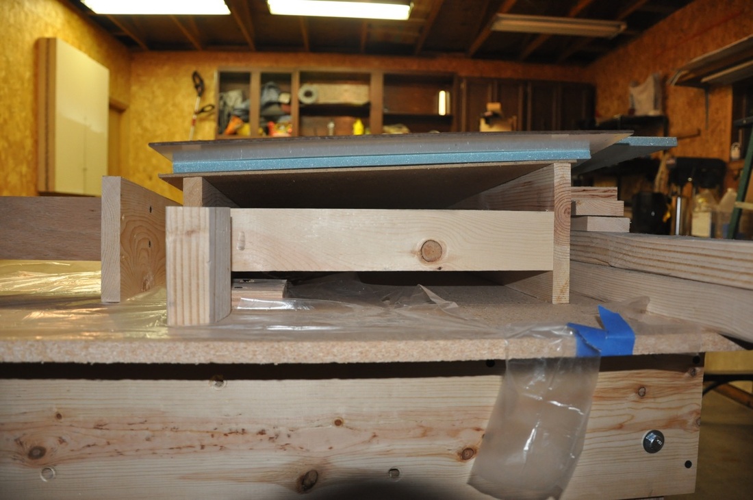
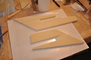
 Triangular clamping block.
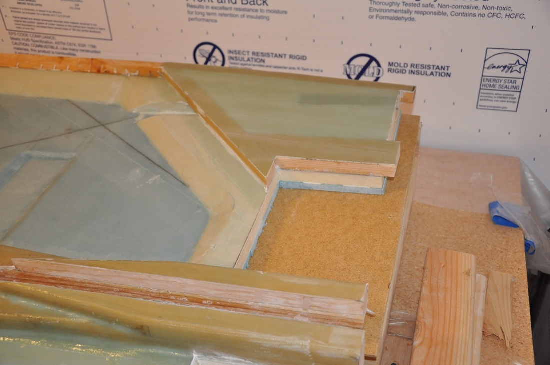
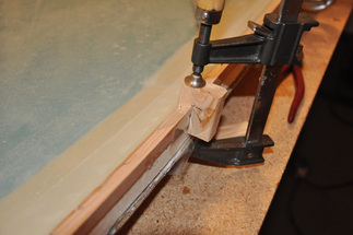
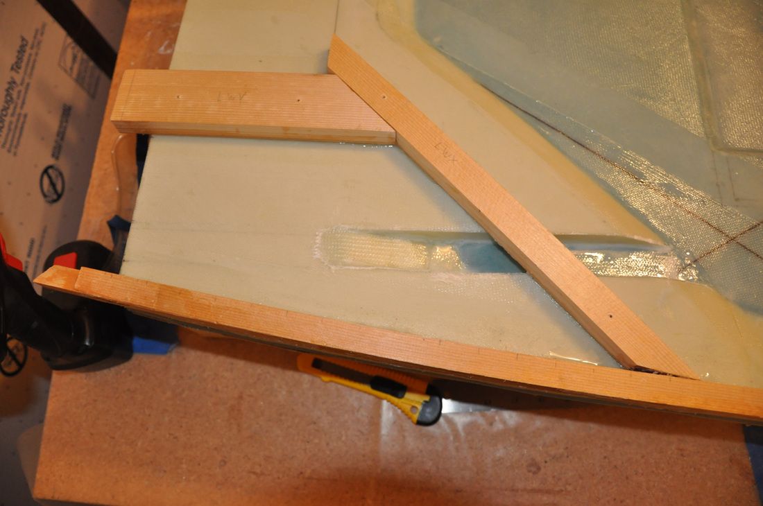
The placement of the lower longeron is stated in the plans as needing to be "exact" and if not perfect, make it perfect. To do this, the top edge of the lower longeron was marked off based on the top edge of the upper longeron. The original side when fine with most of the marks right on where they should have been. The second side wasn't cut as well since I had to cut the foam with the masonite on the jig (didn't want to take it off and disturb the proper setting). I ended up a bit short on the foam so the lower longeron hangs off a bit. Review of the next chapters shows that a bit of this wood gets cut off in the process. I checked the overhang and it's within (sometimes right at) the point where it'll be cut, so I should be okay. A reference line was drawn along the top of the longeron to mark it's location for guiding the permanent installation. To assist with clamping, small clamping blocks were made by cutting a 45 degree profile that matched the wood. This gave a clamp a flat surface to grab that wouldn't smash the tapered edge of the triangular wood. Easy to make with a band saw and can be done with a jig saw. Make several in case they break. Once clampled in place, holes were drilled for finishing nails to help hold in place and to key the piece to the correct location.
Next came the point to actually attach the pieces using flox. The areas where all wood was to attach was sanded over (only needed a bit since the area was previously peel plied). The pieces for LWX and LWY were also cut out. The plans don't specifically mention it, but the pieces should have 45 degree angles on them for all but the lower part that meets up with the lower longeron. If you go by the plans numbers, there will be a small gap (as you can see, I went by the plans). I don't know how bad this is since they are attached all along the side, but I went ahead and filled the area with flox just to be safe. The clamp blocks were used for the lower longeron with release tape between the wood and the block (don't want things sticking!). Finishing nails were used to set the pieces in place and keep them from moving. Weights were added where needed and clamps plus nails used everywhere else. After cure, a 20 inch piece of triangular wood is added on top of the lower longeron on the end to double it and make a square profile. Relief cuts were added to allow it to bend and many clamps were used to hold it in place. Make sure to add release tape to the clamps to avoid attaching them.
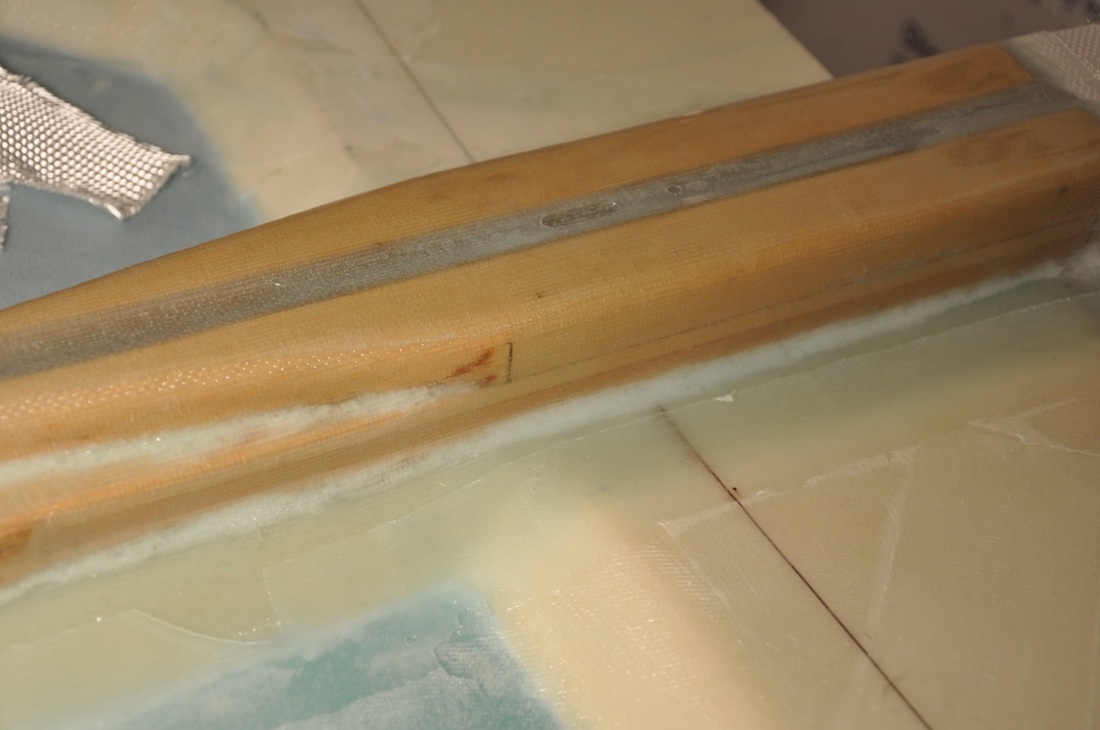
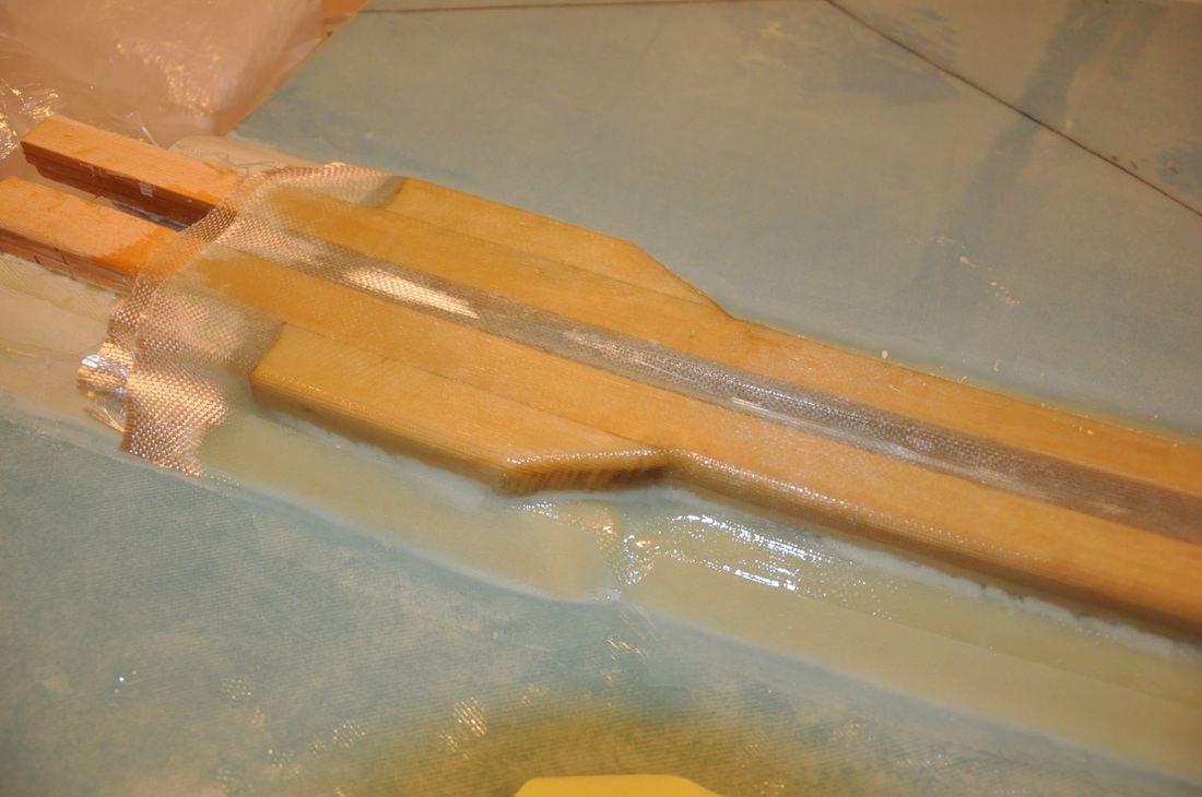
The next layup is four plies of UNI across the upper longerons. Just so happens that the width of the UNI roll is the same width as the four layers with a bit of extra. So I rolled out one length of glass, then folded twice to get the four layers. The folds were cut so that it would lay flat. Micro was placed in the corners of the wood to help the glass transition from surface to surface, then the wood was wetted over prior to the first layer. Each layer was wetted out, then the usual plastic peel ply, then last check for bubbles and voids. When none showed up for awhile, the area was covered and heated to cure.
Unfortunately, the bubble monster attacked big time. When I came out to check the cure, large voids have formed all long the piece. Ironically, most were on the right side piece (the one had to rebuild a second time). I must be cursed on this side for some reason. Oh well. My guess is that even though I had things patted down well I created the large voids when I increased the heat to help cure the piece. Probably should have allowed it to harden, then increase the temp. Anyway, time to break out Chapter 3 and learn how to do some repairs. Some were small enough to only require a filling with epoxy. Others were large enough that a full blown repair was needed. On the right side, I had several large voids in a row that it was easier to just remove the glass from the entire area and treat as one repair. Repair is done by remove the glass all the way to the non debonded area, then sanding back 1 inch for every ply (so this case a total of four inches) tapering it from one layer to the next. Since the glass was UNI, I didn't need to taper across the strands, just with them. You thin lay out the same glass in the same orientation. Once done, you cover the area with 1 ply BID. To sand the area back, I found my angle grinder with a sanding disk made quick work of it, though you can very easily go too far with it, so using it to do the majority and then sanding by hand to get the rest works well. The layers show up as a contrast change as you sand through. There will be a line that separates one layer from another, though hard to photograph. If you're lucky, you'll never had to find out, but it's probably going to happen sometime. With the repairs made, I could move on to finishing the chapter.
Unfortunately, the bubble monster attacked big time. When I came out to check the cure, large voids have formed all long the piece. Ironically, most were on the right side piece (the one had to rebuild a second time). I must be cursed on this side for some reason. Oh well. My guess is that even though I had things patted down well I created the large voids when I increased the heat to help cure the piece. Probably should have allowed it to harden, then increase the temp. Anyway, time to break out Chapter 3 and learn how to do some repairs. Some were small enough to only require a filling with epoxy. Others were large enough that a full blown repair was needed. On the right side, I had several large voids in a row that it was easier to just remove the glass from the entire area and treat as one repair. Repair is done by remove the glass all the way to the non debonded area, then sanding back 1 inch for every ply (so this case a total of four inches) tapering it from one layer to the next. Since the glass was UNI, I didn't need to taper across the strands, just with them. You thin lay out the same glass in the same orientation. Once done, you cover the area with 1 ply BID. To sand the area back, I found my angle grinder with a sanding disk made quick work of it, though you can very easily go too far with it, so using it to do the majority and then sanding by hand to get the rest works well. The layers show up as a contrast change as you sand through. There will be a line that separates one layer from another, though hard to photograph. If you're lucky, you'll never had to find out, but it's probably going to happen sometime. With the repairs made, I could move on to finishing the chapter.
Instead of making the plugs for the electrical conduit covers, I decided to make the foam inserts and form the cover in piece saving the creation of a plug. This was done by a couple of other builders and made sense. What I failed to realize was that the wood is lower than the foam and I didn't sand the foam flush prior to glassing the cover part. So I have a small bump in that area now. I looked farther into the plans and the only thing I saw that was a problem was that I'll have to do some sanding on the landing gear bulkheads to get a proper fit. This isn't something that can happen just doing it this way. If you follow the plans method of making the cover, it'll still end up too tall if you don't sand the plug down, so either way you go make sure it's a bit lower to flatten out the area. The foam is 0.75 inches and the wood is 0.7 inches. Anyway, I used a piece of mylar to set the foam down on to give the cover area a flat surface then wetted out. It turned out okay.
I cut out BID to cover the entire surface. For some reason I thought this was a better idea, but what I should have done was just glass the trough and not any of the surface. This would have probably worked better. At any rate, I got a nice cover custom fitted to the piece without having to make a plug. Unfortunately, there is a slight bump where the cover is since it couldn't be sanded down. It's not much and should only take a slight shaping of the landing gear bulkhead to fit in. The foam was placed in the cavity after the 1 ply BID tapes were added and the area wetted down with epoxy, then micro was used to fill in all gaps and prep the foam surface. The 6 plies of BID were put over the landing gear area, then a piece of mylar was used to do plastic peel ply and remove all the air and excess epoxy, then it was carefully removed and peel ply added over the area as per plans. I only had strip type peel ply, so I had to use several strips. When cured, the layup was nearly air free (maybe one or two very small bubbles down low, but nothing to worry about). This is how the plastic peel ply really makes a difference in the layup. After removing the peel ply after cure, all the excess glass was trimmed from the edges.
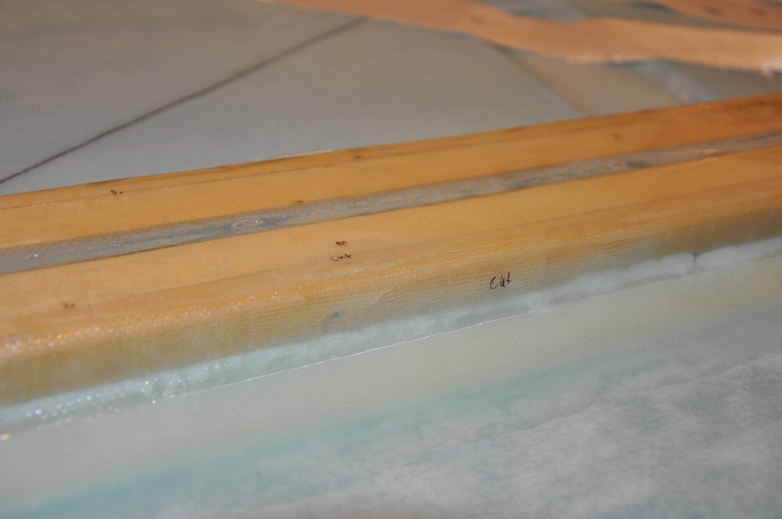
Next up was to trim the sides to their final shape. You're going for a final length of 101.75 inches. The front edge gets cut straight down the line through the wood and the foam. The back only cuts the foam away as the wood will be used to fit the firewall to. I found that my right side (cursed right side!) just barely had enough length to meet the 101.75 inch length, so I was cutting right up to the edge of the foam in the center. To draw the cut line over a contoured surface, I set the piece at the angle required, then leveled the laser and directed the line across the top. I then traced this line on the surface and had a cut line over contours! A jig saw made short work of cutting the material off. For the aft section, the center spar cutout was measured out and drawn. The fein tool did the cutting as it was much easier and cleaner to get in there and cut the foam and glass out. The same was done for the electrical conduit area. Wood was trimmed to 0.5 inches as directed in the plans. All excess glass from around the piece was trimmed and there you have it! Two completed sides! Unfortunatly, my weights weren't stellar. The left side was 1 pound heavier than average and the right was 2 pounds heavier. This follows how many repairs I had to make to each side (the right had more than the left). It's not a deal breaker, but one wants to be as light as possible. So now I'm 3 pounds heavier than needed. Also, the repair areas aren't ones that get cut out later (like the strake openings), so I don't get to remove some of it either. At least their done and we can head on to assembly!
Next up was to trim the sides to their final shape. You're going for a final length of 101.75 inches. The front edge gets cut straight down the line through the wood and the foam. The back only cuts the foam away as the wood will be used to fit the firewall to. I found that my right side (cursed right side!) just barely had enough length to meet the 101.75 inch length, so I was cutting right up to the edge of the foam in the center. To draw the cut line over a contoured surface, I set the piece at the angle required, then leveled the laser and directed the line across the top. I then traced this line on the surface and had a cut line over contours! A jig saw made short work of cutting the material off. For the aft section, the center spar cutout was measured out and drawn. The fein tool did the cutting as it was much easier and cleaner to get in there and cut the foam and glass out. The same was done for the electrical conduit area. Wood was trimmed to 0.5 inches as directed in the plans. All excess glass from around the piece was trimmed and there you have it! Two completed sides! Unfortunatly, my weights weren't stellar. The left side was 1 pound heavier than average and the right was 2 pounds heavier. This follows how many repairs I had to make to each side (the right had more than the left). It's not a deal breaker, but one wants to be as light as possible. So now I'm 3 pounds heavier than needed. Also, the repair areas aren't ones that get cut out later (like the strake openings), so I don't get to remove some of it either. At least their done and we can head on to assembly!