Chapter 8: Headrests And Seat belts
This should be a fairly quick chapter as there aren't too many involved items to do. This is where the headrests are made as well as the shoulder support, rear heat duct, and all the attachment points for the seat belts.
Tips And Hints
- Use the carpenter helper tool to get actual slope contours when making the seat belt re-enforcement blocks and the shoulder support for a better fit.
- Build and install the nut plates prior to attaching the shoulder support. Instead of cutting slots and floxing in place, drill a few holes in the nut plate aluminum to allow flox to come through and help lock it into position. Install after the 1 ply BID is in place on the inside.
- The nut plate lug will be slightly out of round to provide a locking feature that makes threading the bolt in difficult. This is normal.
- When making the transition piece for the heat duct, use vinyl electrical tape to wrap the foam. It'll conform to the contours better and still provide release.
- Make the seatbelt brackets, drill all holes, but hold off on installing the brackets. They will just be in the way while working on the fuselage and could get damaged in the process.
This chapter marks several departs that we will be making from the plans. The plans version of headrests is one of the few things that I feel makes the plane look old and out of date. I realize that they're simple and offer storage space, but I dislike the down grade in appearance they create and the amount of forward view they take away from backseat passengers. Since they offer no rollover protection, I'll be replacing these down the road with something a bit more elegant at the cost of some storage. The other departure is the external step. Since I'm doing a forward hinge canopy, I have have entry and exit on both sides of the plane. I also didn't want to have a step protrude that I could easily hit my leg on, so I'll be following suit as others did and make a retractable step at some point. I'll probably wait till near the end when I know where it will best work at. Other than fairing in the wider area, the heat duct should be to plans.
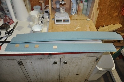
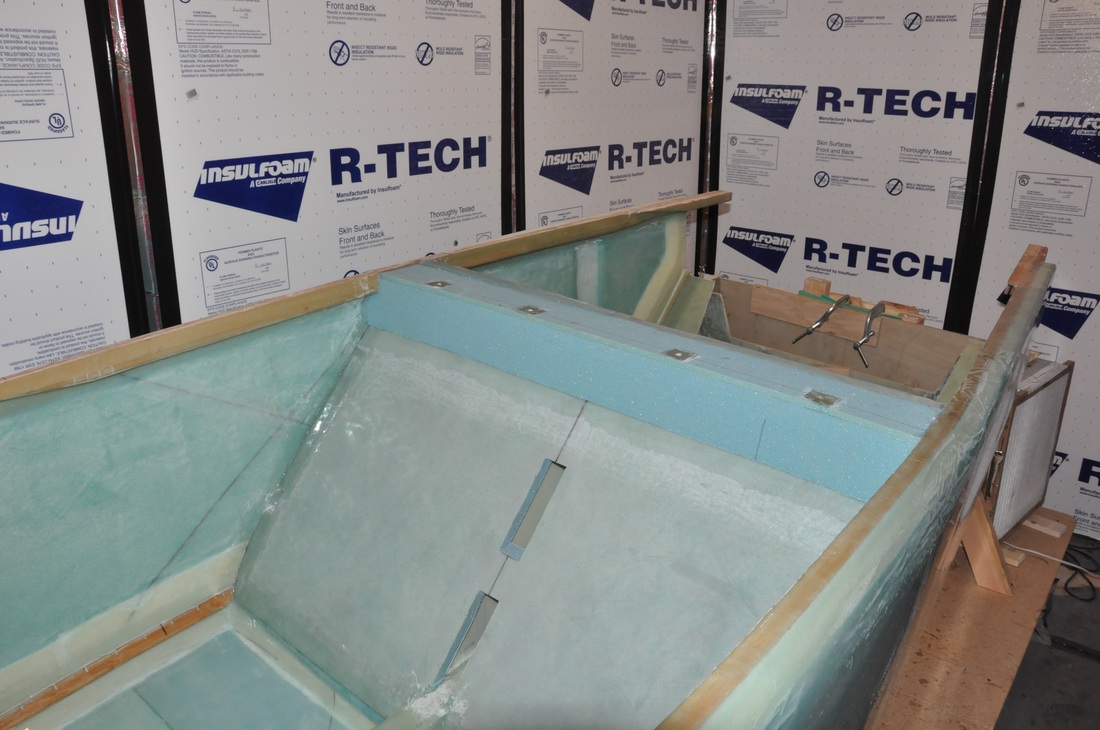
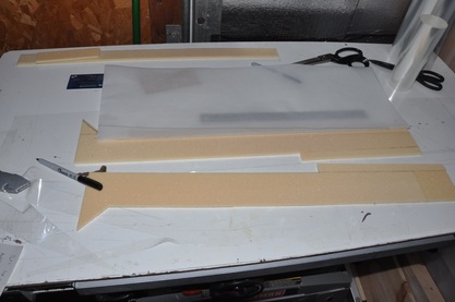
First things first, I started the construction of the shoulder support. This involved cutting out two lengths of 3/8" PVC foam (same as the sides). One is cut longer and will have the sides contoured to fit the longerons. The other is shorter, rectangular, and makes up the top of the brace. One edge of each piece was cut at a 45 degree angle to fit the seat better. I again used my table saw to accomplish this angle cut to get a consistent cut that was smooth and quick to do. Next I used the carpenter helper to get the longeron and side angle for cutting out of the vertical piece. I captured the profile, then traced onto the foam, then cut out using a utility knife. I did not drill the 1 inch hole as I don't know exactly what locking mechanism I'm doing yet, but it can be added on later if needed. Next the four squares were measured out to the plan's locations and cut out using a utility knife. These will make up the spots where the seat belt attachments go.
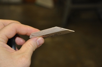
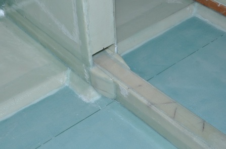
Next it's time to cut out the wood inserts. These use the remaining pieces of birch plywood from the firewall installation. I had plenty left due to only building the bottom and sides (I plan to make a slightly larger area up top down the line). I cut out the four 1.25" square pieces for the seat belt points in the shoulder rest and the four pieces for the floor attachment. The plans didn't specify a size for these. Looking at the images, I found that one dimension that matters is that the piece must be 2 inches long before the bevels in order to accommodate the angled aluminum bracket for the seat belt attachment. The other dimension is mostly dictated by the curve of the fuselage. Since I had plenty of material, I cut the pieces 3" x 3" initially, then trimmed down to fit. For the length that accomodates the bracket, I beveled the edges 0.5 inches each to leave a 2 inch full thickness area. By the way, it's probably best to make this bevel after doing the first (made it harder to do the first).
For the fuselage side bevel, I used the carpenter helper to get the angle at the middle location of where the re-enforcement was suppose to go. From there, I tried to trace it onto the piece, though this proved difficult because I had already cut the first bevel forcing me to trace the outline onto the first bevel. I recommend doing the side profile first then the edge bevel since the edge is a fixed length that is independent of any part shape. At any rate, with some trimming and sanding with a sanding disk on an angle grinder, the pieces were trimmed to fit and marked for installation later.
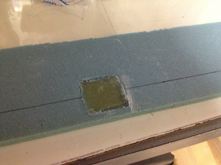
Using 5 min epoxy, the 1.25" wood squares were added to the cutouts in the shoulder brace foam. I made sure to put plastic under the foam to avoid gluing the piece to the work surface. Since the fit was tight, it was hard to get the epoxy along the edges and stay there as the piece was inserted, but it didn't take much to set them in place. The pieces sit flush with the foam on the bottom but leave a gap on the top for fiberglass later. I followed the plans and beveled the edges of the foam for the fiberglass. I then placed packing tape along the border of each spot to keep epoxy from getting on the foam surface when the glass re-enforcement was added. The plans talk about making three ply of BID in a 5" x 5" size. From this you cut 4 x 4 grid to make your 12 ply BID squares to go over the wood inserts. I followed this, though it was difficult to cut the fiberglass when it was wet without it pushing out some. Either my scissors have gotten dull or it was just a bit much to cut at one time. The amount of distortion was low and I was still able to use it. I placed each piece (minus the plastic protective film) in the gaps centered as much as possible. After all 12 were placed in, I peel plied the surface and squeegeed to get as much air out and flatten the pieces out. Some filled in level and some dipped slightly at the edges, but nothing that was going to ruin the day. This was allowed to cure. After cure the holes were drilled out on the drill press (just because it was easier and more accurate). This is ahead of the plans, but will make it far easier to do and you won't be left with particles foating around in the shoulder rest when attached.
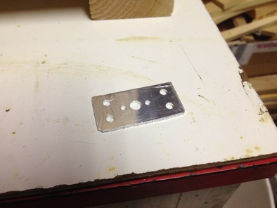
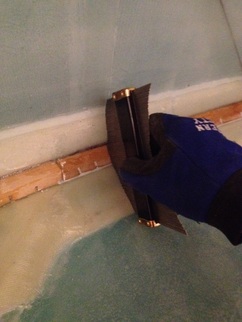
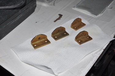
Since I didn't like the idea of how to put the nutplates in after the shoulder support was glassed in place, I decided to make the nutplates now and add them while I could still get to the piece. This would allow easier positioning and requires no slot cutting (if you dropped one inside, I don't want to think of the pains that you would have to go through to get it out). To make the plates, you first cut out strips of 1/16" aluminum flat stock. To this, you drill a 1/4" hole in the middle for the bolt. Once that was cut, I used a bolt to hold the nutplate lug in place so the retaining holes could be drilled. I had to drill with a 3/32" drill bit to make the initial hole, then widen it with the lug removed to a 7/64" drill bit. This allows a solid aluminum rivet to fit through without making the hole on the lug bigger (must be some strange hole size that I don't have). I then drilled four 3/8" holes at the corners. These will allow the flox to push through and help grab the part when installing. Once done, I washed the parts with soap, rinsed, then did the alumiprep and alodine process to protect the parts. Again, as with the firewall, it may not be necessary but corrosion protection won't hurt and this way even the cut holes are protected. It will also aid in flox adhesion.
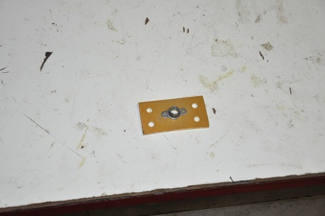
I checked the forum for how you're suppose to install the aluminum rivets. I saw things from using an actual rivet press tool to hammering down the end to using vise grips to smashing it down (I think Nat even suggested that one). Considering that these only hold the lug in place and keep it from turning when the bolt is installed, I'm not as worried about keep the full integrity of the rivet (I'm not building wings out of rivets), so I chose to use the hammer method to flatten them down. It's as close to what an air hammer does to install rivets, so I felt that was the best method for the time being. When I get to more important parts, like canard controls, I'll probably use an actual rivet press tool. At any rate, other than being close quarters, I was able flatten the rivets. With that, all my plates were ready for installation.
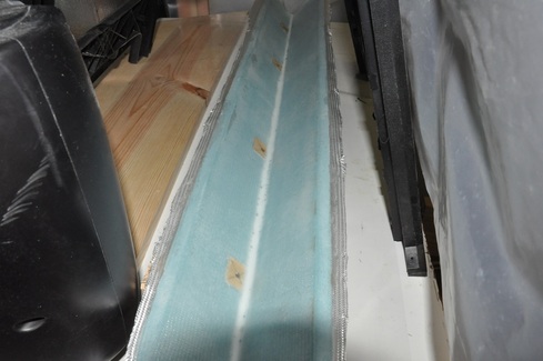
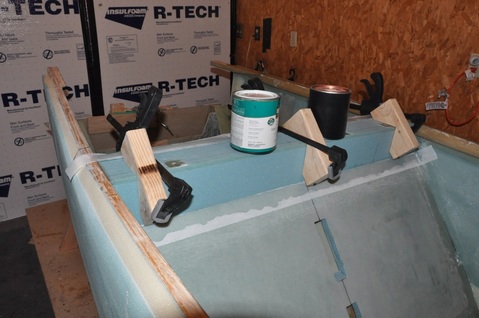
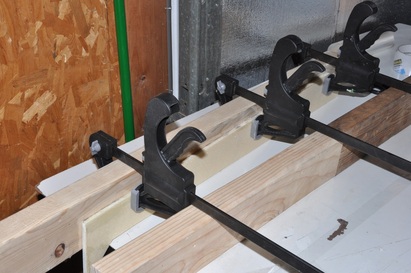
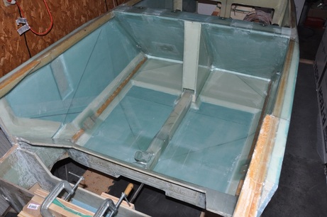
Before installation of the nutplates could take place, the two pieces of foam for the shoulder support need to be glued together then glassed over on the inside. I made a jig with 2x4 wood pieces with two 45 degree cuts made to create an angled 90 degree holder. This will hold the foam at the correct angle while glassing is occurring. I drilled screw holes to run some long dry wall screws through to hold the foam down. The foam was glued with 5 min epoxy following the plans. Once attached in the blocks, the edges along the angled cuts were sanded to round off for easier glass laying.
In all my excitement of making good progress, I neglected to install the nutplates ahead of time as I had planned. This occurred because I was following the plans (not necessarily a bad thing) and neglected to make a note in the right spot to avoid the issue. So, here's the steps that I would have taken:
This should work well and you will have nutplates attached with no holes to cut. Unfortunately, I was unable to test this, so someone will have to let me know how it works.
- Micro and glass the inside with 1 ply BID. Make sure to run a bead of micro down the middle to help the glass make the transition in the corner.
- Mix up some stiff flox. Apply the flox on the ends where the holes were drilled trying to avoid the area where the bolt hold is. Press into place. Use an AN4 bolt and enough washers to make a tight fit to hold the nutplate in place without having to thread too much into the nutplate. This will avoid losing the locking feature down the road when you install the seatbelts. You will have to wax the bolt to avoid epoxy sticking and you will have to separate the thread around the holes.
- While setting, sand the area where the piece will attach. Vacuum up any dust.
- Leaving the bolts in place and attach the shoulder support per plans once the epoxy has set up enough.
- Wet out and peel ply the area and leave to cure.
This should work well and you will have nutplates attached with no holes to cut. Unfortunately, I was unable to test this, so someone will have to let me know how it works.
Here's what really happened. I glassed the inside of the brace as instructed leaving the 1/2 inch overhang dry. The seatback was sanded in preparations for the layup. Once the layup had tacked up, I applied flox to the mating edges (along the length and on the sides), placed in on the seatback, clamped into place, then wetted out the exposed glass strips and peel plied the layup. I filled in any gaps along the piece with flox to ensure a strong bond. After I stepped back to admire the job and see the seat transform, I looked over at the plans and saw my nice alodined nut plates sitting there. Doh! For a split moment I contemplated taking it off, but decided it would make more of a mess and cause more problems that it was worth especially since there's already a different method in the plans. So I'll be doing it the plans method. My advice, write in a note where you need to install them.
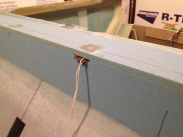
With the brace now floxed in place, it was time to look into installing the nutplates. The one nice thing about the plans method is that the plates will be well anchored from turning when completed. I decided to install these prior to glassing the outside just so I wouldn't have to cut the glass to put the plates through. The goal was to cut a slot big enough to fit the plate through with a small amount of space to allow some flox to be on the plate itself so it would have good adhesion on both sides. The bolt used to hold it in place will be waxed to avoid sticking to the flox if it gets on there. Washers will get used to avoid having to completely thread the bolt and lose the locking aspect.
After floxing the nutplates in place, the shoulder brace gets 2 ply BID wrapped over it and onto the seatback (front side). I neglected to notice the part where the plans said to either cut the BID wide to lap 1 inch onto the surroundings or BID tape later. I cut the glass flush so I had to BID tape afterwards. Not a major deal, but it would have been faster to just extend it. The glass gets trimmed flush with the back edge of the seatback. Before starting, I used the router with a roundover bit to round the front edge. It's quick and leaves a nice consistent rounded edge. Due to the slight warp in the seatback, one side of the brace wouldn't push flush up to the top edge. So when I microed the surface over, I had to put some extra on that side to level the area. The areas that will get the UNI tapes across the seatbelt points were covered with peel ply to facilitate the glass bond later.
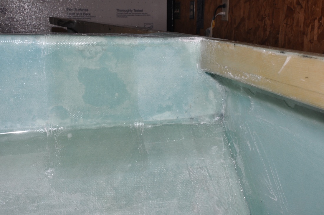
So I must have been tired or maybe I had too much chocolate, but I thought I could glass both layers at the same time since I've had good luck with the plastic ply method. I wanted to keep the fibers straight and it's so much easier to fix the cloth while it's dry. So I got the straight fibers, but the next day I had major delaminations and dry spots along the front side (the top was fine probably with the help of gravity). So after taking a moment for personal reflection, I broke out the fein tool and cut the BID off the front. Half of it came off with no problem. The other half actually resisted quite a bit (where it was layed up properly). I kept the piece as a show and tell. Before proceeding with the repair, I made sure all the surface was well sanded to allow a good bond. Then the area was repaired as needed. You will note the blotchier appearance on the front side where some of the foam was pulled up and some wasn't. So I learned not to take shortcuts and stick to the method at hand on this one. It's not as pretty as it was before, but it should be good to go now.
Next is a small layup that tapes place over the seatbelts. This one is easy to miss because it tells you to do this under a picture rather than in the steps. It consists of 4 inch wide 4 ply UNI. It starts on the seatback, wraps over the shoulder support, then wraps around the backside of the seatback. Most builders by now will realize that back edge is going to be a nuisance for the fibers to lay straight. What I should have done was just taken the router and rounded over the entire edge. What I tried to do instead is locally sand over the edge to round it out. I must not have rounded it enough because I was still fighting bubbles, so I pulled it up enough to run a bead of somewhat dry flox along the edge to round over the area better then lay the glass back down. This worked very well, created a smoother transition, and should be strong enough for structural purposes.
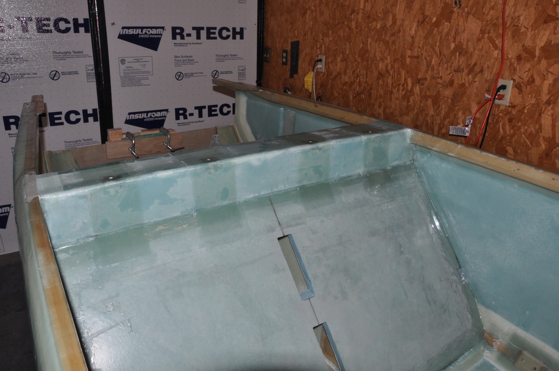
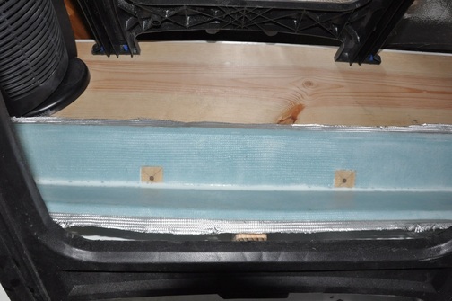
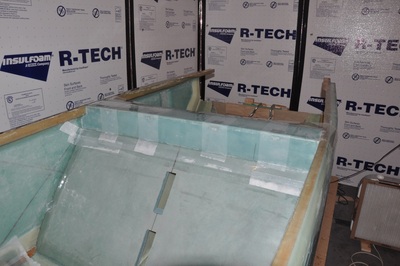
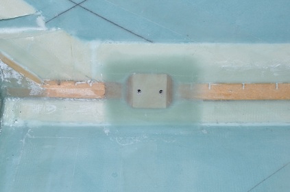
Next came the front seatbelt lower attachments. I grabbed the previously marked wood pieces, verified they still fit properly, the installation area was sanded including 1 inch past where the wood goes, then floxed them into place and covered over with 7 ply BID. The BID was wetted out onto plastic to ensure all air was out between the layers. The plastic was peeled back on one side and pressed into place overlapping 1 inch onto the sides past the wood. I used peel ply over the entire surface since it conforms to compound curves better than the plastic does. This gave me the nice smooth edges and prepared the surface for the metal attachments.
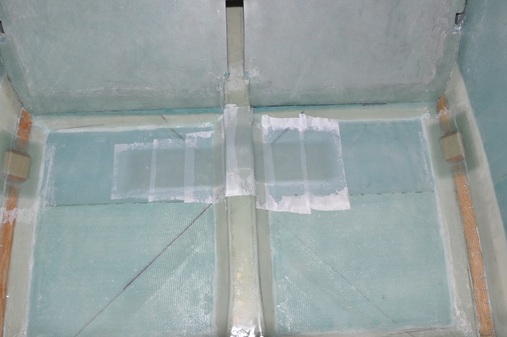
The middle seatbelt attachment also gets 7 layers of UNI across it. I tried to cut the pieces at slightly different widths to help feather the edges. I tried to wet out all the layers on plastic then apply, but the curves of the heat duct were a bit much for it. It would be better to do 1-2 layers at a time for this one. Otherwise the outer layers just pull on the inner layers and you get voids in there. I had to peel some layers off (a real miss when you're working with cut UNI). Eventually it was flattened out and peel plied to smooth the edges. By morning I did have some small bubbles that required a bit of filling, but it still turned out okay. When I do the back, I'll probably try plastic wrap to see if it'll work better as well as do less layers at one time.
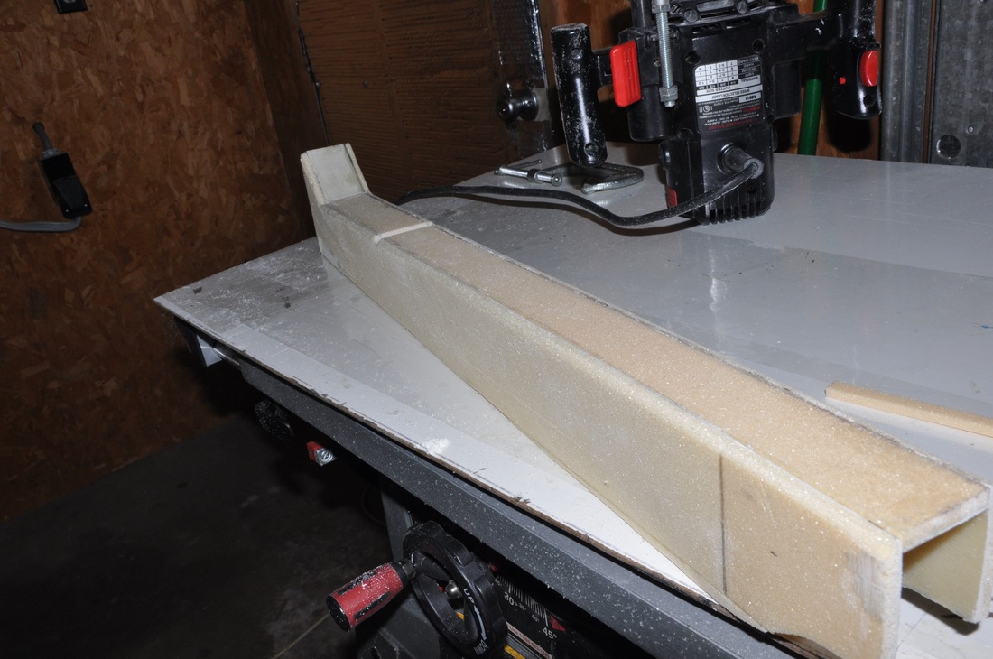
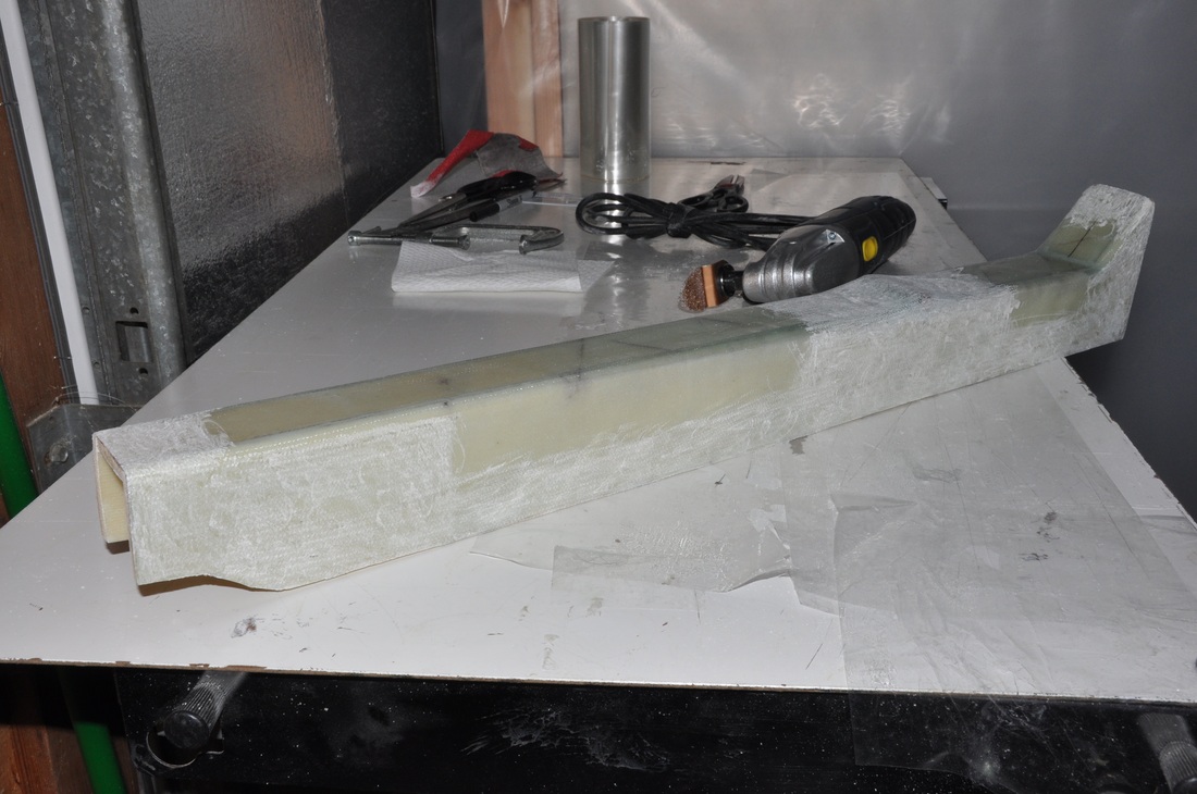
Getting close to finishing this chapter! Next up was the rear heat duct. This was constructed very similarly to the front one. Hardest part was capturing the bottom contour. I taped paper to a board, ran the board front to back over the area I wanted to capture, leveled the board with the upper longerons, then used a pen attached to a piece of wood to trace onto the paper as I slid the wood across the bottom. This drew the curvature out for the bottom offset onto the paper. All I had to do was use the two height markings on the plans to position the profile correctly on the foam and carve the foam to that profile (Sounds like a lot, but really isn't). This worked very well and only took minor corrections to fit. I used the carpenter helper again to capture the profile of the spacer where the duct goes up to meet the front duct. Once carved out, the sides that will become the inside were microed and glassed over with 2 ply UNI. Plans says you can use either UNI or BID and since I had large scraps of UNI I went that route.
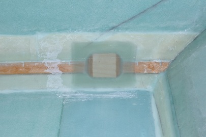
After cure and trim, I sanded the area where the internal baffle will eventually be added while it was easy to do. then I covered a 2x4 with plastic to act as a form. A standard 2x4 is 1.5 inches in width, exactly what the heat duct is suppose to be. I mixed up 5 min epoxy with some flox and floxed the pieces together using the 2x4 form. Clamps were used to help hold the pieces together during cure. Since this cures quickly, I could move right into adding the baffle. The baffle was glassed on both sides previously just to make it easier. It was floxed in place using 5 min epoxy as well. After trimming off excess epoxy, the outside edges were rounded over with a router and a depression was sanded into the top for the seatbelt tube (similar to before). Fit of the duct was checked again before proceeding.
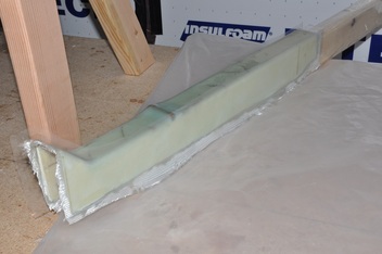
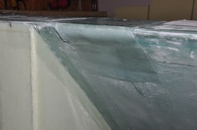
For glassing over the outside of the duct, all the non-foam surfaces were sanded and the aluminum tube was alodined then floxed into place. Large flox fillets were placed on either side of the tube and tapered down to the foam. This will allow the UNI to sit properly. Micro was then added to the entire surface (might have been easier to do before the flox, but it still worked). A 7 ply tapered UNI strip was constructed (again following the plans from chapter 6) and placed over the tube overlapping onto the baffle surface. The entire thing was covered with 2 ply BID while sitting on the 2x4 form to help hold the shape. The surface was then plastic plied to smooth it out and remove excess epoxy and trapped air.
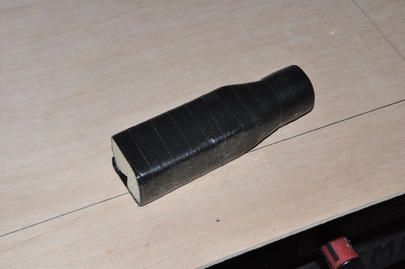
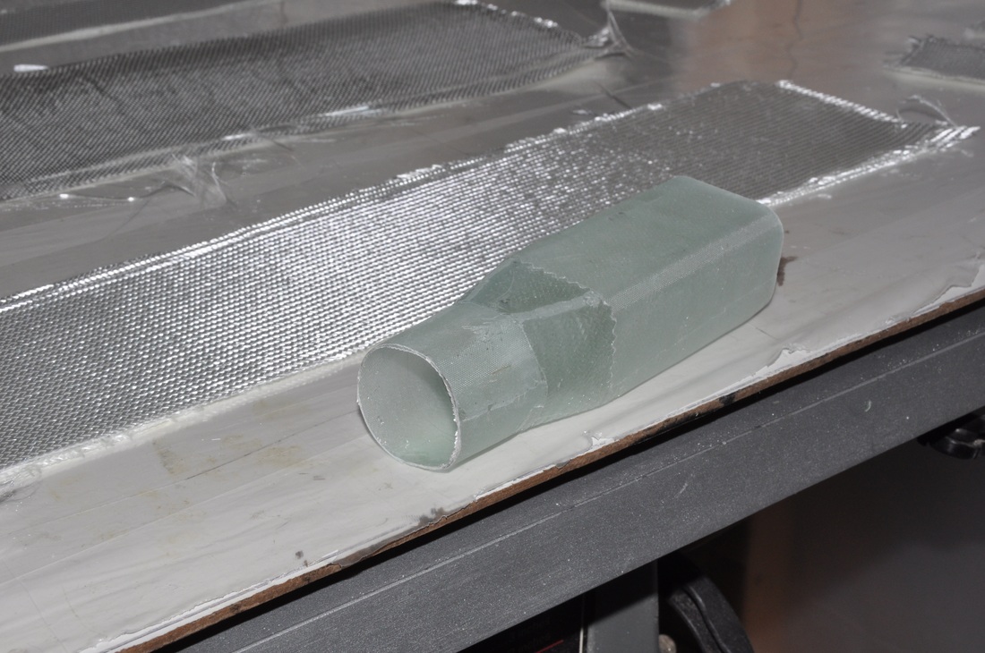
After trim, the heat duct was ready to get the transition piece added. Urethane foam (the really soft stuff used to make the NACA) was used to make the piece. It starts out square on one end and transitions to a circle on the other. I found that the small mixing cups were the same diameter called out in the plans, so I used one to make my guide for creating the circular end. After carving the piece to shape, I followed the suggestions to use electrical tape to cover the piece for release. Electrical tape has a lot more stretch to it so it fits the curves better and worked out well for me. Once covered, the piece was wrapped in 2 ply BID. I peel plied the surface as well as possible to help smooth things out. After cure, you basically have to tear the foam out to remove the plug. All in all, it turned out well.
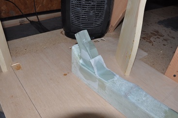
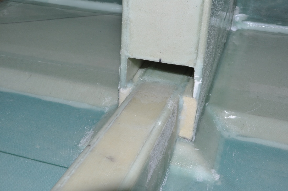
Once cured and the plug was removed, the transition piece is added to the back of the heat duct. I cut the hole for the piece as far back as possible to minimize how much it will intrude on the back seat passengers. After sanding and filing, I got a fairly tight fit that I didn't have to hold the piece in place. Flox was added and the piece was fitted in place following the angle of the baffle. BID tape was added to the joints and peel plied to smooth out. This was left for cure. All the surfaces that will get glassed over in the next steps were also sanded at this time to make things easier. Now it's ready to install.
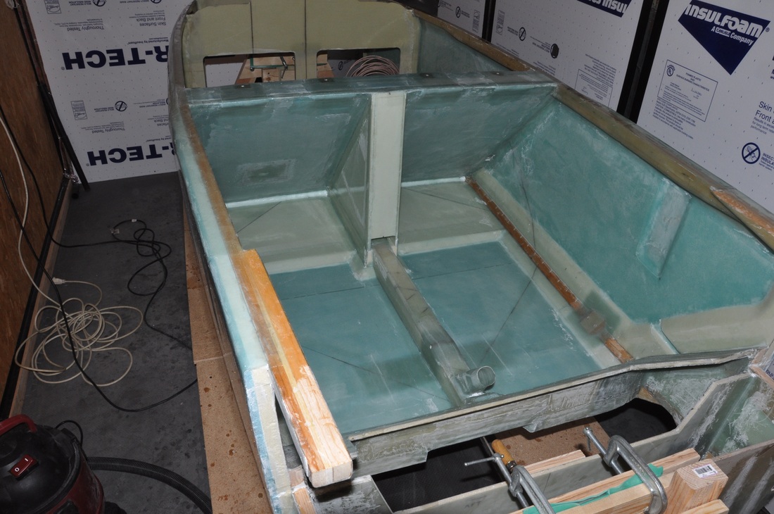
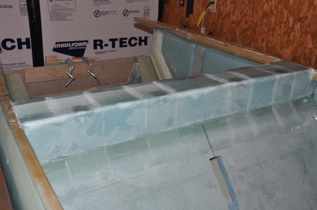
To install the duct, it was test fitted in place to see how well it conformed to the bottom and sides. After trimming and sanding, a good fit was obtained, so the piece was floxed into place and all joints were BID taped. After cure, the 7 ply BID and UNI were added over the middle seat belt attachment and peel plied to smooth out. With that the heat duct was in and the end was near!
I hadn't drilled out the holes for the outer seatbelt points yet as I hadn't made the brackets yet. First, a piece of angled aluminum was used to create the brackets. They were cut out following the plan's dimensions. Holes were located as close to what the plans showed (though some dimensions were lacking. Afterward, these pieces were alodined for protection.
Next, each bracket was marked for it's location and used to drill the bolt holes through the wood supports and the lower longerons. By marking the brackets, the bolts should line up later in case the holes are not the same from bracket to bracket. I used various tools to line up the drill to drill as perpendicular as possible. They all looked good, so hopefully they're straight. I don't have the counter bore I need right now, so I'm going to wait on doing these. It doesn't matter much as I don't plan to install the brackets till I have the inside finished anyway so I don't hit myself on them. For now, they're ready to go with just a counter bore needed.
The last thing that I needed to finish for this chapter was to add a couple of small fairings to the side of the heat duct to blend it in with the wider seatback brace. This was due to the change I made to the plans, so it's not in the instructions. I could have just rounded the edge and glassed the bit of exposed foam at the time of installation and left it at that, but I wanted to have something that flowed better. I used the same foam as before (the same foam used to make the side spacers). Using the carpenter helper, I got the curves of the bottom, traced it onto the foam, then cut it out. The sides were tapered and the top edge was rounded over for easier glassing. 2 BID was applied to the top and sides only then the pieces were floxed into place. Since these are purely cosmetic, they will not be BID taped. It does add a small amount of weight, but it will aid in giving the back seat passengers something to keep from stubbing toes on and should help dress up the appearance. With that, this chapter comes to a close.