Chapter 9b: Landing Speed Brake
So this is it! Your first moving part of the airplane. This section covers the construction of the speed brake and the installation of the electric linear actuator motor. Note that the plans covers a manual version of the brake. There have been discussions as to which is better. Here's a quick breakdown of both:
Manual Speed Brake
Pros
Pros
Manual Speed Brake
Pros
- Quick to deploy (manual lever pull)
- Auto retracts if airspeed gets high enough
- Takes up more space in front seat
- Auto retract action can be very quick possibly slamming the lever down onto your hand
Pros
- Adjustable deployment angle
- If it has a position potentiometer, it can display the deployment angle in some EFIS settings
- Frees up space in the front seat console
- Lighter than the manual system
- Have to figure out the install yourself (or copy someone's install, like mine)
- Slower to deploy (about 8 seconds to full open)
- Does not auto retract on go-around without a secondary circuit (see the circuit on Marc's site. Go down to the Landing Brake Safety Interlock for the details).
- May take up slightly more space in the back seat
- Does require electricity to operate
Special Parts Needed / Where Used
- Firgelli Automation linear actuator: # FA-PO-150-12-04 (150 lb, 4" stroke, built in limit switches, and position potentiometer)
Tips and Hints
- If using the electric linear actuator, have it on hand before planning out the landing brake mounting locations.
- To make installation of the landing brake easier, use a spherical rod end bearing and tap the end of the actuator (or get one already threaded) to allow for adjustments.
- There appear to be two hinge types listed for the landing brake. One is a bit wider than the other. Both will work, but the foam aft of LB-23 will need to be tapered more than is shown in the images to allow the glass to be put over the surface and still allow the hinge to be attached.
- Transfer the location markings for the aluminum slugs to the hinge so that they can be drilled out with the hinge attached.
- When sanding the foam in the landing brake depression, remove a bit more extra from the cambered parts just to make sure there's room later for the brake. It can always be filled in with micro.
- If you want a long lasting hinge pin for the brake (or any other hinge), here are the items to order from McMaster Carr:
- High-temp Chemical-resistant Tube Sleeving .066" Id, For 14 Awg Wire (Item # 5335K17) - Get 2x the amount you need.
- 303 Stainless Steel Tight-tolerance Rod, 1/16" Diameter (Item # 88915K11)
- Try to make a stout jig for the landing brake. They have a bad tendency to warp a bit. Make one that attaches at several points. The plan's version isn't enough for most people.
- If you want to make the bolts to the landing brake flush, it will require flush head bolts and extra glass. See instructions below.
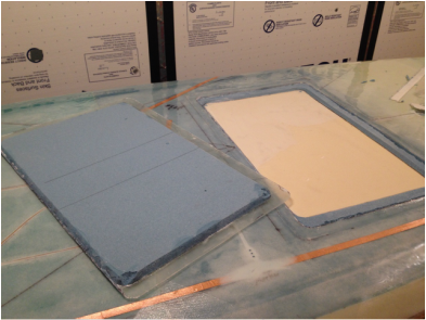
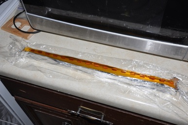
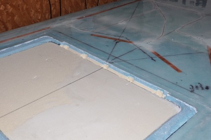
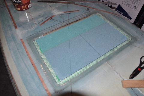
This is the first moving part that you get to make in the plane. To cut the brake out, I used the fein tool with a cutting blade on it. I drew an outline so that I would have a cutting line to follow. Careful cutting along the line eventually severed the glass on the brake from the surface. Unfortunately, despite the taping job that I did, the brake was stuck in place. I had to do a lot of prying to get it up. In hindsight, I should have put the tape on the brake foam as well rather than just the bottom foam. Eventually, I was able to get it free but not without tearing out foam along the edge. So there will be some repairs to do.
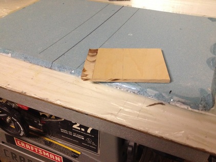
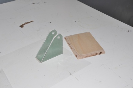
The next step was to cut out the wood parts for LB-19 and LB-23. I cut LB-19 one inch wider to accommodate the use of the electric actuator and having the wider seatback brace. To make the hinge recess, I used my router with a straight bit, first set it flush to the surface, then used the hinge to set the depth guide so that when I fully plunged the router it would only go the distance of the hinge. Real easy process. LB-23 was lengthened from 10 inches to 17 since I made my brake full length. This will hopefully help it not to warp later on in life as some have had happen. The original brake used 4 screw attachments on LB-23, so four is plenty for holding the brake. I elected to add a fifth attachment since I was spreading them out and to help with any twisting forces. It may not be needed, but seemed like a prudent thing to do. These spots were marked out on both sides of the wood so that it would be easy to both set the aluminum slugs and to drill and tap the holes later.
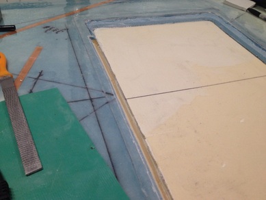
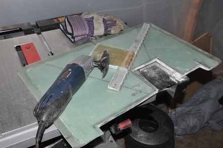
Next, I did the preparations for finding the 2.25 inch location from the seatback. Luckily, I had already drawn in the location of the bulkheads previously, so this was an easy feat. Turns out the point occurs right in the tapered foam area along the front side of the landing brake just slightly up from the urethane foam surface. I drew a guide line as well as my 17 inch limits. Next I used a block of 2x4 that was cut to a 45 degree angle as a guide for cutting the foam out. I used the fein tool to do this and just used very light pressure stopping whenever I came to resistance (the glass surface). After making the 45 degree cuts along the front and back, I just pried the pieces of foam out to make the slot for LB-23.
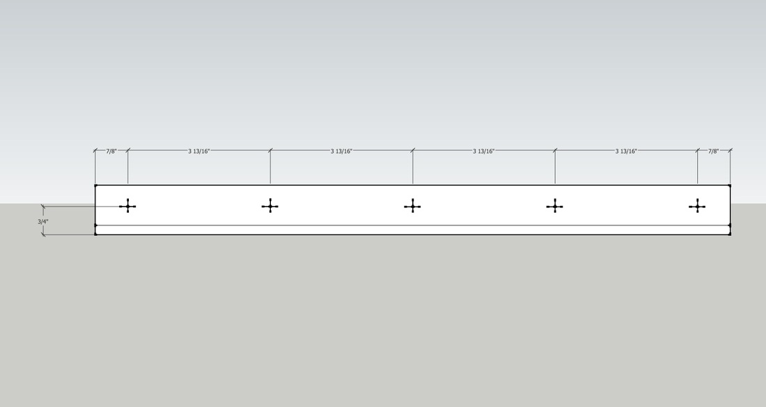
Next the hinge preparations took place. Since I made my brake full length, I need a longer hinge. This will hopefully make it less prone to twisting. Since LB-23 was widened to 17 inches, the hinge was cut to 17 inches as well. I also cut the 5/8" aluminum slugs out of 0.25 inch thick 2024 (per plans), however, I added a fifth slug since I spread out the hinge. This changes the placement a bit. I left the outer most ones at the plans spot, but the others were equally spaced between these. I attached a drawing showing the placement. In case you can't read the numbers, it's 7/8" from the sides, 3 and 13/16" between each mark, and 3/4" from the bottom of the beveled edge. I made sure to mark both sides of LB-23 for the center points of the aluminum slugs for easier reference later.
I then cleaned and alodined the slugs and the hinge. The hinge must have some type of protective coating (oxide perhaps) as the alodine didn't touch it much, but the hinge holes definitely didn't have anything on them. Certainly doesn't hurt to do so. In order to do the hinge, I didn't feel like doing the brush on technique as I wanted to be thorough, so I made a trough out of aluminum foil that was the same size as the hinge then lined with plastic wrap. This worked well and kept the chemicals to a minimum. I didn't treat the hinge pin itself because I plan to replace it with the teflon and stainless steel wire that is mentioned in the forums (more on that later).
Once dried, I followed the plans and 5 min epoxy set the slugs to the front side of LB-23. I also glued the hinge to LB-19 with 5 min. For this, I attached one edge 9 inches from one side and the other 4 inches from the other side. This places the brake in the right spot for the actuator to attach to (I hope). Remember that my LB-19 is 4 inches wide instead of 3. This arrangement only offsets the wood from center by 1 inch. Next, you are suppose to attach 0.025" aluminum plates to LB-23 where the hinge goes. Most people suggest three layers of duct tape. I checked it and the duct tape measured 0.024", should be close enough and easier to remove. I didn't see much discussion on how to attach the hinge to the duct tape. I went ahead and tried 5 min epoxy and hoped the duct tape would stick enough to install the hinge and be easy to remove later. It worked quite well as long as I wasn't too rough.
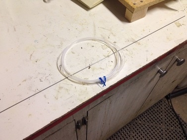
Before going too much farther, I decided to do the teflon hinge replacement that I read about. You use to be able to buy a kit, but now you just buy what you need. It basically consists of two parts: teflon tubing and a stainless steel rod. The easiest and best place I found to order these was McMaster-Carr. They carry a lot of things and I'll probably be ordering other items from them as well. What you want are the following two items:
The idea is that the stainless steel rod fits inside the tubing and the whole unit is placed inside the hinge line. This makes a low friction, non-corroding pin system. From the archives, where I got the dimensions of the parts, it says it's suppose to make the fitment tight. I measured the original pin and it was 0.0635" where the tubing was close to 0.066" so it is a bit wider. The directions also say that you normally have to slit the tubing then shove with great force to get it to fit. My stainless rod just slid right into the tubing and then slid right into the hinge line. Maybe a different hinge is used for the ailerons and rudders. We'll see. So I don't have the incredibly tight fitment for the landing brake, but it was just as good if not slightly tighter than the original and won't corrode. I will have to make sure the pin is retained somehow though.
- High-temp Chemical-resistant Tube Sleeving .066" Id, For 14 Awg Wire (Item # 5335K17)
- 303 Stainless Steel Tight-tolerance Rod, 1/16" Diameter (Item # 88915K11)
The idea is that the stainless steel rod fits inside the tubing and the whole unit is placed inside the hinge line. This makes a low friction, non-corroding pin system. From the archives, where I got the dimensions of the parts, it says it's suppose to make the fitment tight. I measured the original pin and it was 0.0635" where the tubing was close to 0.066" so it is a bit wider. The directions also say that you normally have to slit the tubing then shove with great force to get it to fit. My stainless rod just slid right into the tubing and then slid right into the hinge line. Maybe a different hinge is used for the ailerons and rudders. We'll see. So I don't have the incredibly tight fitment for the landing brake, but it was just as good if not slightly tighter than the original and won't corrode. I will have to make sure the pin is retained somehow though.
|
Now the hinge with LB-19 wood insert needed to be added. First the foam was removed from the glass in the area where the hinge needed to go. Next, the hinge and wood were trial fitted into the area cleared out and checked for fitment. Once the fit was right, the pieces were floxed into place and allowed to cure.
|
|
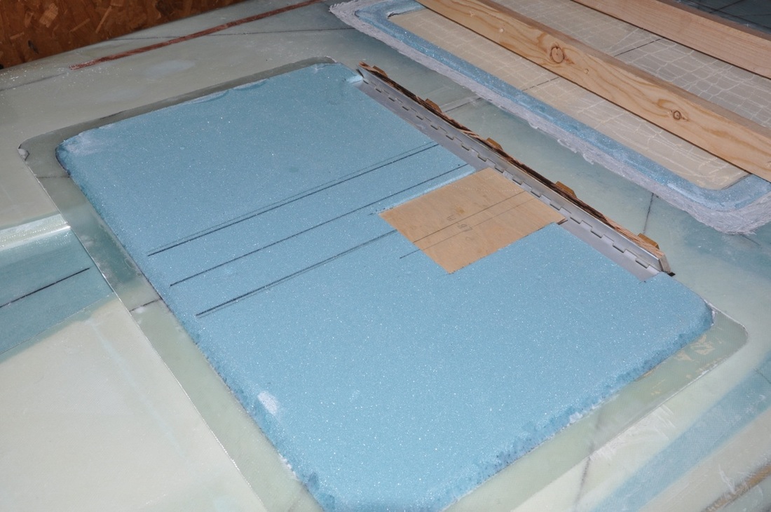
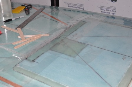
Next up was the foam preparation. This entails taking away 1/8" from the landing brake depression area. I thought about the router but didn't want to make a jig to hold the router at a specific height, so I followed the plans method for cutting 1/8 inch slots in the foam and sanding till they disappear. This worked just fine actually. The blue PVC foam was harder to sand than the yellow urethane foam. It likes to tear rather than sand, so I'll have some repairs necessary later. I also rounded over the glass edges as much as possible to aid in the layups that were coming soon. The other thing that needed to be done was remove foam where the aluminum slugs are located on LB-23. These were cut and pried out with various tool.
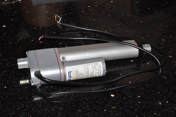
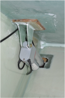
As with most builders, I'm using the linear actuator for the brake deployment. No one really has a good set of drawings out there for placement, so I'm going to try to correct that. I went back to Google Sketchup to lay out an outline of the seatback, floor, and the door so I can get some idea of placement. Based on other builders, 65º of opening appears to be about ideal for what the system is able to do, so I targeted that amount. If I get a bit more, no problem. I wanted to actuator to remain as perpendicular to the board as possible without being in a strange location. It will be offset some, but should be fine. The actuator I bought was the Firgelli 150 lb 4 inch linear actuator with position indication and built-in limit switches (part # FA-PO-150-12-04). Using the measurements from the motor, I set up the theoretical attachment points. My attachment to the brake itself was about in the same position as Bernard Siu, so I must be on the right track. The other end was going to take a bit more to figure out. Most attach theirs to the brace side, but not wanting to spoil the space inside, I decided to mount my to the seat back. The plan is to make a bracket that attaches to a piece of 0.25" birch plywood (same as the firewall material), and glass over with a few plies of BID. This will give a good mounting structure and provide a hard point to stop the motor from poking through the seat in case the plane collapses onto the brake while it's open. I'll fine tune to positions once the brake is glassed and installed.
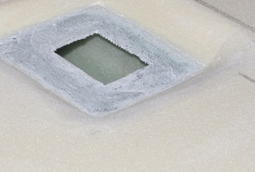
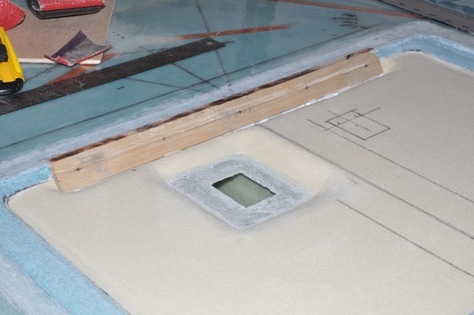
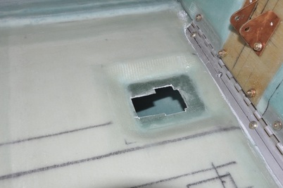
So next was cutting the opening for the brake mechanism. I measured the width of the arm and added for the bolt plus a small amount for wiggle room. I marked this out on the foam guessing what the length of the cutout will be needed. Once I know for sure, I'll adjust my size in the diagram to fit. Be careful when marking this hole as the fuselage is upside down and the landing brake will be upside down if you're looking at the unglassed side. The hole should be on the right side of the fuselage when it's upright (or the left side when upside down). You can see that I started drawing on the wrong side, but didn't start cutting before I saw the mistake. I just used the fein to cut the slot out, then I cut the foam at a 30º angle to taper it. I left a flange of glass only around the hole 1 inch wide to allow for a full glass to glass bond (like BID taping). Don't know if it's necessary or overkill, but it's what's there now. The foam was sanded smooth to allow for good contouring of the glass.
The next part had me stumped for a bit. The plans show the foam both not being tapered at LB-23 and tapered. When I checked the hinge, it will not fit in the space if the foam is not changed once that area is glassed over. A message to the forum found out two things: One, the hinge that was specified in one spot is slightly wider than the hinge that is suppose to go there. Two, Most everyone has had to taper that foam or cut the hinge down to fit. I decided that I didn't need to change the hinge out and that I would rather taper the foam than cut the hinge down. So I sloped the foam in this area. This will also provide room for the bolts on the landing brake later. Again, the foam was contoured for easier glass layup.
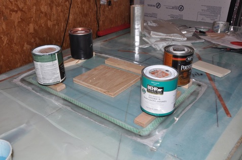
Next was the moment to install LB-23. This is done by adding micro to the slot for LB-23 then pushing it into place with the brake attached. Two wood boards are attached to the brake (I used hot glue to do this) to hold the brake in position as well as brace LB-23 properly in it's space. The hinge should be level with the fuselage bottom as per the plan. After cure, the hinge is popped off of LB-23 and the brake is removed while still attached to the boards. The boards will help hold the brake shape while it gets glassed. With LB-23 attached, the drill points were transferred to the hinge for easier reference later. Clearance around the brake and the depression is checked to make sure there's room for the glass that will get added next. I placed electrical tape over the hinge line to keep epoxy out and I used clear packing tape to tape over the hinge that will eventually attach to LB-23.
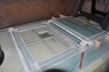
Glass was cut for the layups. The depression gets 2 ply bid all over then another ply in the motor opening and along LB-23. The back of the landing brake gets 3 ply BID all over. All glass to glass areas were sanded to roughen up for the layups, everything vacuumed clean, then dry micro was applied in all the corners to smooth out the transition and to fill in gaps or missing foam. Micro was spread on the rest of the foam for the layups. The glass wetting went as normal, but there was great fear that all the joggles on the brake depression were going to cause issues (they did). So extra time was spent trying to get the glass to lay down in these areas. All the edges of the contours were peel plied while the flat foam areas were plastic plied. This was left to cure at 70ºF, then after the initial cure it was post cured at 112ºF (that's what my heater could get the area up to at the time) to hopefully avoid some of the brake warping I hear about. Time will tell, though the brake will stay on the jig for as long as possible.
After cure, all the peel ply was removed. The areas where I used plastic looked great with very little trapped air. The peel ply areas didn't fair so well. I had several small voids in that area that had to be repaired. I should have weighed down the areas, but that might have caused other problems. With the repairs made, the glass was trimmed and any rough or jagged spots were sanded out. Once the repairs were done, the brake was fitted back into place, and it no longer fit! What's going on? It appeared two things had taken place. One, the brake warped just slightly in one corner (actually, the brake was almost perfectly flat rather than slightly curved). Two, the cambered parts of the brake depression (where the brake foam was originally cut out of the bottom) were not sanded back enough and there wasn't enough clearance. Tom Holt was gracious enough to come by and take a look to confirm that's what had happened and the best way to tackle it. We agreed that it would be best to try to warp the brake back with some heat and at the same time cut out the camber and reglass. Looks like another learning experience!
To do the repair, I set up the jig for the brake, weighed the middle to make the brake curve like it's on the fuselage, then heated it with an electric heat gun making sure to keep it moving across the area that needed to soften. I made sure to get the front and back. It apparently worked because when I was done the brake appeared to have the right shape. As for the depression, I used the fein to cut out enough foam and glass to widen by 1/4". This was to allow for the extra room for the brake and for the thickness of the glass since an extra layer of BID must be added to the repair. Strips were cut out and the area was glassed over and peel plied since there were lots of contours and micro will be added to flush mount the brake. After cure the peel ply was removed and the fitment was rechecked.
Before attaching the brake, I decided I wanted to do a modification to allow flush mounting the attachment hardware. I read in the forum Marc Zeitlin's suggestion of adding a few plies of BID then using flush head bolts to avoid having exposed hardware or having to make a large bump with micro to cover over. I made two pieces of 4 ply BID that fit over the hinge line and LB-19. These will give the extra material needed to allow the bolt heads to have something to hold against. I used plastic ply to smooth the surface over, remove air and excess epoxy, and leave a nice transitioned edge that is smooth and not jagged. Once the final positions of the bolts are known, the holes were drilled and countersunk. The hard ware used was the following:
- 4 x NAS1203-3 flush head bolts (for area over the hinge but not the wood)
- 2 x NAS1203-7 flush head bolts (for the area over the wood insert)
- 6 x NAS671-10 nuts
- 6 x AN960-10 flat washers
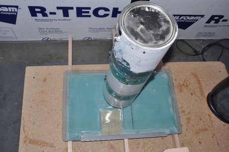
Looking more at my brake, I finally decide that I've butchered the thing too much and now it's too much of a mess to leave it as is. So, despite not listening to the wife sooner (about 2 months ago, sorry Sweetie), I decide to rebuild the brake. The plan is to remove the hinge and wood insert since they are just fine, then cut new foam, protect the area around the brake opening, and then glass over the surface. The nice thing is that this will exactly take to the contours of the opening. This time a better jig will be built and the brake attached. Then glass the other side over after adding the hinge and wood insert. So first thing up was to remove the original brake and hinge, then prep the brake depression. I added the 3M tape just as before to make the support for the glass so it was flush with the foam. I used mailing tape over this and onto the surrounding area for release and to help contain the wet epoxy. I used stir sticks under the foam to elevate it for where the glass layers will eventually go on the back. I also took scraps of the same type of foam for the brake and attached them with the hinge method and 5 min epoxy. I then cut out a piece that was the same size as the original, rounded the edges, then beveled the edge to the same cut as the original. I checked the height to the tape and made any needed adjustments. I redrew the centerline and cloth angle lines that were originally there before.
Once the brake was sitting well inside the depression, I made alignment markings so I would know where to position the brake when glassing. The area was taped up to avoid epoxy sticking to everything, then the brake was covered in micro and 2 ply UNI was added to the surface and extended onto the foam tape. I wetted the glass out past the tape a bit so I would have plenty to cut back to the right shape. The excess glass was trimmed away and the surface was plastic plied to smooth it out, remove air, and get rid of excess epoxy. I had to lightly weigh down some areas to make sure the brake conformed to the shape of the area. This was left to cure.
Next was the hard part, emotionally. I used the fein to cut out the wood insert and hinge. It was easy enough, but then I had to figure out how to remove the glass directly attached to the pieces. Using a heat gun, I was able to soften the glass enough to slowly peel it from the surface. I liked this method because it didn't create a lot of dust, came up mostly clean, and wasn't very difficult to do. Once the glass was removed, I cleaned off the foam and flox stuck to the hinge. It was now ready to be added to the new (and hopefully better) brake.
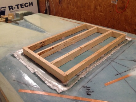
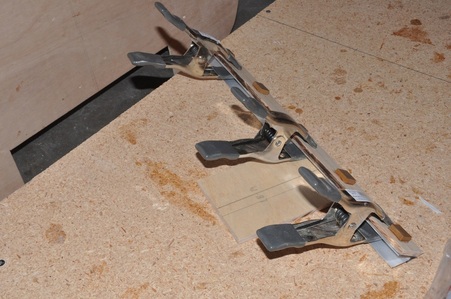
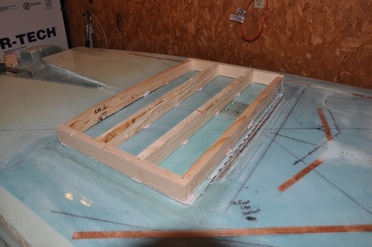
The new brake was attached to a new jig which uses two sides pieces with four cross members that cover the entire length the of the brake. This allowed me to use bondo to stick the jig to it in at least 20 places while the brake was still sitting in the fuselage depression. The bondo should hold the piece in the correct shape for the final glassing. I believe what happened last time was that the previous jig (which was only two boards as stated in the plans) wasn't enough to hold the correct shape and the brake glassed in the warp state when the 3 ply BID were added. This time, it should glass in the correct shape. I even have bondo holding the outside flange to ensure that the shape is kept.
With
the brake now secured on the jig, I prepped the surface as before
(micro filled gaps and corners, floxed the corner joints near the
hinge), and applied the three ply of BID to the brake. I peel plied the
edges due to the contours and plastic plied the top surface to remove
excess epoxy and trapped air. Once cured, the peel ply and plastic was
removed and the piece checked over for any defects. As a last effort to
oppose any warping, I post cured the piece while it was on the jig at
80ºC for at least 6 hours. This will get most of the available glass
transition (Tg) temperature that is available for this system and should
stiffen up the material fairly well. We'll see. After trimming the excess glass off, I rechecked the fit. Would you know it, the same side was still up a bit. So I measured everything and checked for what would cause the fitment issues. I did find one issue which was the hinge attachment point was slightly high on one side. I couldn't really re-tap the holes for such a short change, so I elongated the holes on the high side of the hinge and moved the hinge down. I'll later fill the gap somehow to keep the hinge from moving or just cut another hinge out to replace it. This move helped a lot, but it was still high. So I tried heat warping it again. I used a heat gun and warmed a line across the brake where I needed it to bend till the epoxy softened. I placed stir sticks underneath the brake to hold it up off the depression in the area I was not trying to warp, then I weighed down the top to bend it into place. This was left overnight to cool down slowly and lock into place. The next day I was rewarded with a brake that was fitting within reasonable tolerances! (Finally!) I then added 4 ply of BID to the outside where the bolts go, plastic plied the surface, then reattached the jig to it to hold the shape. I might consider reheating the structure to relieve any stress in the system and cool down to make sure it holds that shape. I can finally move on!
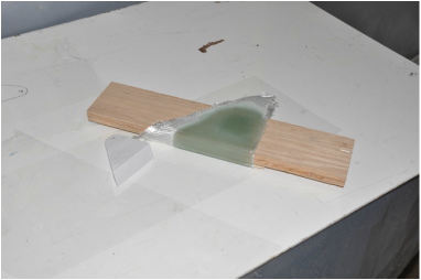
Now I can focus on the attachment point to the fuselage for the linear actuator. I thought about making a bolt in part, but then decided to just go ahead and fiberglass in something instead. First thing was to decide where the mounting point had to be. I used Sketchup to just make lines at the appropriate angles for my setup. I used Bernard Sui's site to get an idea of where the motor needed to attach. It appears that 65º of opening is about what you can get on this setup, so that's what I went for. To achieve that, I tried to set the attachment point so that the motor would be pushing on the brake at as close to 90º through the motion. There will have to be compromises, but I think the setup will work well. It's actually very similar to other's so I know I'm in the right area. The sketch with dimentions is below for reference. I used James Redmon's Berkut 13 site to base the design of my brake mount. I didn't use the same shape as his layout is a bit different than mine. From my Sketchup drawing, I need about 2.75" out from the seatback. 0.25" of that will be a wooden backing for impact protection in case I land on the belly with the brake out (Note: must have catastrophic failure and loss of main landing gear for this to happen). I made a bracket in Sketchup and printed it 1:1 so I had a template to draw on the plastic for fabric sizing. Finally, all those triangular scraps I had became useful. So the bracket was made with 8 plies of BID then 8 more plies added at the bolt hole area for a total of 16 plies at each end. I then wrapped this in plastic and formed over a 1 inch thick board. The plastic will smooth the glass out and will keep the fiberglass from sticking to the wood. After cure, it was trimmed out to size based on the template. I made a template of the bracket below. Keep in mind that I'm taking my best guess on what will work but it's unproven. It should hold up nicely to normal use, but what happens in an accident is unknown.
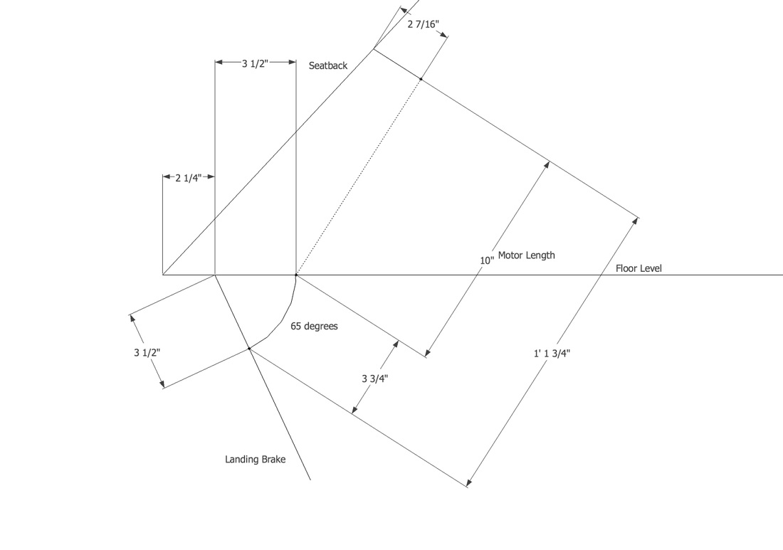
Landing Brake attachment layout
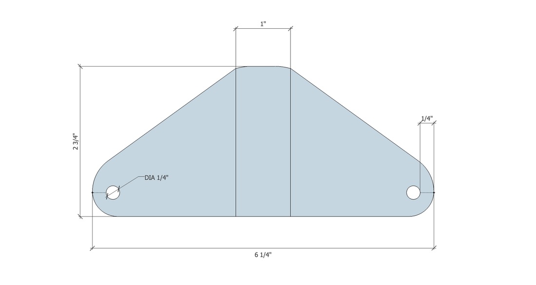
Bracket Template
After the bracket was made, I cut a piece of 3" x 5" wood from the leftover 1/4" ply used for the firewall. I angled and rounded the edges for easier glassing. This was floxed into place where the motor needed to go and 2 ply BID was added on top of it and onto 1 inch of the existing structure. This will be the base for the bracket as well as a protection in case the motor tries to break through the seat. With the motor attached to the bracket and the brake, the brake was pulled shut with the motor fully retracted and the spot where the bracket would be at this point was marked on the fuselage. After that, the motor was removed and the bracket and plate were sanded for glassing with 2 ply BID on the sides and 2 ply UNI running down the middle. The hope is that this is strong enough to hold the motor in place but weak enough to break away if there is an impact to the bottom of the plane with the brake deployed.
The brake glassed in without too much trouble, but it must have moved slightly. The motor was not reaching the limit switch before it contacted the fuselage. So I found that it needed about 0.15" of room more to finish moving. I tried opening the motor to set the limit switch, but found I was going to have to remove press fitted plastic gears and I didn't like that idea much. So instead, I added a 15 ply BID shim to the brake itself to raise the mounting brackets. I will need some longer screws, but this allowed for an easy adjustment that will allow me to adjust without too much issue in the future. The motor now shuts off when it closes! So it took a bit to do, but I don't think it was really any worse than other methods and I didn't lose any space in the seatback brace. We'll see how it holds up.
UPDATE!!
Something that would have been nice to do was modify the end of the motor to accept a spherical rod end bearing. This would allow for adjustments to the length to fine tune the system. This could have been accomplished by drilling and tapping the end to accept an AN4 rod end bearing (same type used in the controls later in Chapter 16).
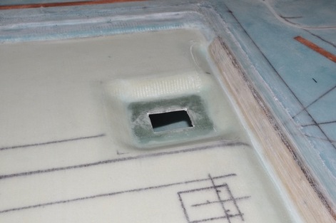
In order to allow clearance for the bolt holding the brake on, I had to trim the hole to make space for the bolt and for the movement of the motor. The motor moves slightly out from the opening as it opens (circular path). The fein worked wonders here. The cutout avoids hitting any of the parts and the motor is able to open and close freely. The hole was made to be fairly small but without really restricting the motor. Works great through several test runs (you know, for scientific research purposes).
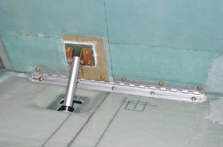
Getting close to finishing this up. I needed to replace some of the hardware and add washers to take up the space between brackets. I used an AN4 bolt of the proper length to attach the motor to the brackets because it was the proper diameter. Nylon locking nuts were used to secure the bolt on. I placed nylon washers between the moving surfaces to reduce wear from movement and also take up the space between the brackets and the motor mountings. This centered the device so there was little movement. The final thing I did was secure the hinge pin. As mentioned earlier, I replaced the standard hinge pin with a stainless steel rod inside a PTFE tube. The pin needed to be secured because my brake was not made to the plans specifications, so I made the pin longer and bent it around and secured it under the outside bolt. I had to use a longer bolt to do so, but the pin will not move now. The same thing was done on the Cessna aircraft that I train on, so it made sense to do it here. You might be able to see the pin on the left side in the image above.
