Chapter 4: Bulkheads
This chapter starts off making the easier pieces since they are flat and are also the least aerodynamic since they're internal. This allows the builder to gradually get into the project without taking on an overwhelming piece like the wings to start. Confidence is built upon from the pieces in Chapter 3 since now it's for real. So let's get started.
Tips and Hints
- Angled cuts can be easily done using a table saw, jig saw, or band saw (like the seatback edges).
- Use the hinge method for gluing foam panels together for the IP and other bulkheads (see Tips section for details)
- Make the IP 0.25 inches longer on the bottom. If you don't need it at assembly, then you can trim it off, but otherwise it'll help to avoid a gap later that many people experienced.
- Before trimming the glass from the edges after cure, shine a light underneath and use a fine line sharpie to trace where the foam starts to facilitate cutting right along the foam. Once you start cutting, there's so much dust it can be difficult to see where to cut at especially on the thicker layups.
- When making the hard point for the landing gear bulkheads, use the foam that is cut out as spacers to help get the same thickness as the foam when it's weighed down.
- When drilling the 1/4 inch hole in the landing gear bulkhead, use the written measurements rather than the drawn location for the hole.
- The firewall template may have one incorrect measurement on it. the opening for the NACA duct is shown as 7.5 inches, but it measured 7.8 inches. However, the important distance is the B.L. 14 located at the lower engine mount. Use this one to decide if you're drawing is accurate. In this case, going by the drawing rather than the 7.5 inch number is better. Also, double check the center line to make sure it's perpendicular. Mine wasn't.
- Make the aluminum engine mount inserts 1.25 inches square rather than 1 inch square in order to allow more adjustment for bolt placement. Go ahead an protect them with something like Alodine. It'll aid in adhesion and you won't have to worry about future degradation.
- Don't cut the holes for the longerons in the permanent firewall just yet. Wait for Chapter 6.
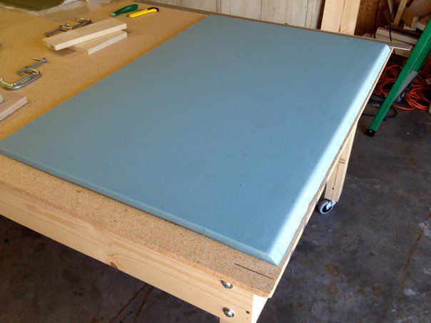 Seatback foam ready for glassing
The first piece of the build is the seat back. This is constructed from a single sheet of 3/4" H45 PVC foam. First it's cut to the dimensions in the plans, then one side is cut at an angle. I cut the foam out using a sharp utility knife and a metal straight edge. This makes for a very clean cut. The angle was done with the utility knife as well using the edge of the table and the metal straight edge as a guide, but I think my table saw set at 45 degree angle would have been a bit easier (Correction, it would have. Worked on other parts). Some have even hot wire cut the edge since you can do this for PVC foam (don't do this for urethane!!). Many ways of doing the same thing. Using sandpaper, the edge of the angle where it meets the top side was rounded over so the glass would lay flat without air bubbles. Once cut and rounded, you prepare your glass fabric by cutting it out over-sized and carefully laying it out to fit. The fabric is set out so that the UNI runs at 45 degree angles both ways. I had to cut a second piece to cover the bit of corner that the fabric didn't reach, but followed the directions for overlapping fabric (or in the case of UNI, butting against the first layer). After rolling up the fabric and placing it to the side, you mix up a batch of micro and then spread it out on the surface for even coverage, then scrape off the excess. Then carefully layout the fabric on the piece making sure the lines are as straight as possible. I ran into a problem where my fabric appeared to shrink despite overisizing it and I couldn't get it to fit without a lot of work. I had also added epoxy first to the foam so that it would soak up into the fabric. I later switched to placing the first layer of fabric before wetting out.
 First side glassed, peel plied, and plastic peel plied
With perseverance, I finally got the fabric mostly in place (it's less than ideal, but it's close) and wetted it out. The second layer went of much better, but I still struggled some. Wayne Hick's suggestion of getting the fabric straight on a piece of masonite, then sliding it off onto the piece would work very well here. I did this for other bulkheads and my work got much better. Using the electric scissors, the glass was trimmed to 1/4 inch (or close to that) to avoid lifting problems, added peel ply strips to the edge for easier adhesion of future layers without sanding, then plastic was applied to the surface and excess epoxy and air was squeegeed out of the layup. The plastic I started using was a 6 mil plastic that was a little harder to see through and had folded lines. This was later exchanged out for clear mylar that made a major difference.
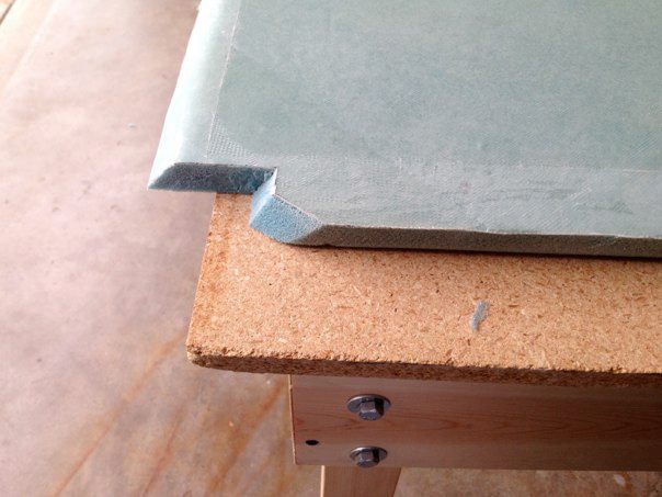 Corner details of seatback
After cure, the plastic and peel ply strips were removed. The contours and excess glass were cut out with the fein tool. I don't see why these cutouts couldn't wait until the other side was glassed as well, so if one wanted to wait, they certainly could. I went ahead and followed the plans. One could also wait until the fusulage assembly to make sure the cuts fit the profile.
After this, the other side of the foam was prepped by cutting the other end with a 45 degree angle parallel to the first. The very edge of the foam at the bottom was cut out to prepare for a floxed corner since it would be a glass to glass transition and this adds strength to the edge. The sides were also rounded and prepped for flox in a similar fashion, but no 45 degree angle was cut.
After this, the other side of the foam was prepped by cutting the other end with a 45 degree angle parallel to the first. The very edge of the foam at the bottom was cut out to prepare for a floxed corner since it would be a glass to glass transition and this adds strength to the edge. The sides were also rounded and prepped for flox in a similar fashion, but no 45 degree angle was cut.
 Other side angled and flox area removed and sanded.
Just before glassing, the foam was covered in micro, the joints were filled with flox using a plastic sandwich bag with the tip cut out, then the 1 ply BID glass was added to the surface. Special attention was given to the sides where the 90 degree transition takes place. Despite this, I still ended up with a couple of areas of lifted glass that didn't want to stay down. So this became my first repair job. They were small and could be fixed with scrap pieces of glass, but still not what I wanted to happen. Just follow the plans for repairs, sanded the area to join and overlap by one inch on the glass. Repairs were easy in this case. Already appreciate fiberglass.
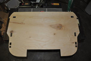
 Seatback completed and ready for installation
Here's the finished seat back after cutting out the center holes for the map pocket and heating vent. I kept to the size listed in the plans, but I will probably enlarge the map pocket hole as many have complained it was too small to easily reach into and made using it a problem. It will require a fancier seat cushion to leave an opening but still provide cushion across the back of the seat, but it shouldn't be a big deal.
 Cutting out IP from Clark Foam
The next set of pieces were the IP, F22, and F28 bulkheads. This started out with tracing the original drawings onto tracing paper. I did this using the method described in the tips section. The tracings were then taped down to the foam and traced out using the tracing wheel method. For long straight cuts, a ruler and a utility knife were used. for curves, I used the Fein tool to cut out the foam. Pieces were then glued together using 5 min epoxy using the hinge method (also in the tips section). Sand paper was used to clean up corners. Once glued together, the two BID and one UNI were added to most of the surfaces as per the plans. For the F22 bulkhead, a doubler is added over the fiberglass to the top of the bulkhead. This then receives more layers of fiberglass to stiffen the area (this is where the canard will attach later). Make sure to taper the doubler well in order to get a good transition with no air bubbles when the fiberglass is added.
 F22 Bulkhead with doubler finished
Peel ply strips were added to the sides and bottom of the bulkhead before the plastic peel ply was added. Once both sides are glassed and cured, the excess was trimmed using a band saw for the outside and the fein tool for the inside areas. Sand paper was used to clean up the edges. Centerline references were added to aid in assembly later on.
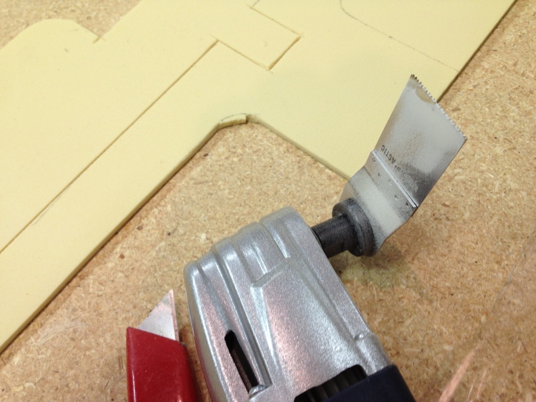
 Traced outline of F28 ready for trimming
When cutting fiberglass flush with the foam, I found it easier to draw out with a fine tip sharpie where the foam started. Though you can see through the glass, it gets harder to see during cutting. The lines help to see the edge of the foam. For thicker glass layups, a light underneath the piece make it easier to see the edge of the foam.
 F28 ready for installation
F28 was the first piece that I had to completely redo. The first piece looked great on one side, but when the other side was glassed I must have squeezed the layup too hard causing air to suck back into the glass. I had lots of dry areas all over the piece (I was past my 10% allowance). The piece was small enough that it was easier to just redo the piece instead of fixing the one side. You might notice that I went for the higher profile on F28 to go for the more rounded nose shape. As stated in the plans, it's a personal preference whether you want the rounded or flatter look. The new piece was much better with no dry areas.
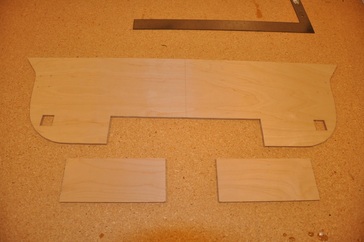
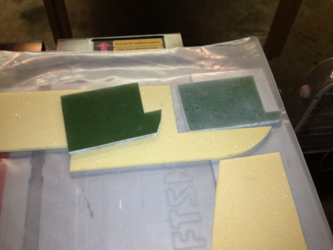 Hard point trimmed for foam. One piece sanded.
Next process was to make the 1/4" thick fiberglass layup. I used 24 layers to make mine, plans say 22. After wetting out the glass on a piece of plastic, another sheet was added on top, excess epoxy was squeezed out, and a flat board was placed over the top and weighed down. Pieces of the foam that were cut out where the hardpoint goes were used to act as spacers for the correct height of the material. However, I found that I was just slightly thicker (0.5 mm I believe) than the foam once cured. 23 layers probably would have been better. 22 would probably be right on track if I squeezed the excess epoxy out more. At any rate, it was close enough, so the pieces were cut out, sanded down for the layups, and glued in using 5 min epoxy. Be careful that the correct foam is used for the landing gear bulkheads. There are two types of 1/4" beige foam used in the construction of the plane, so double check the type before cutting.
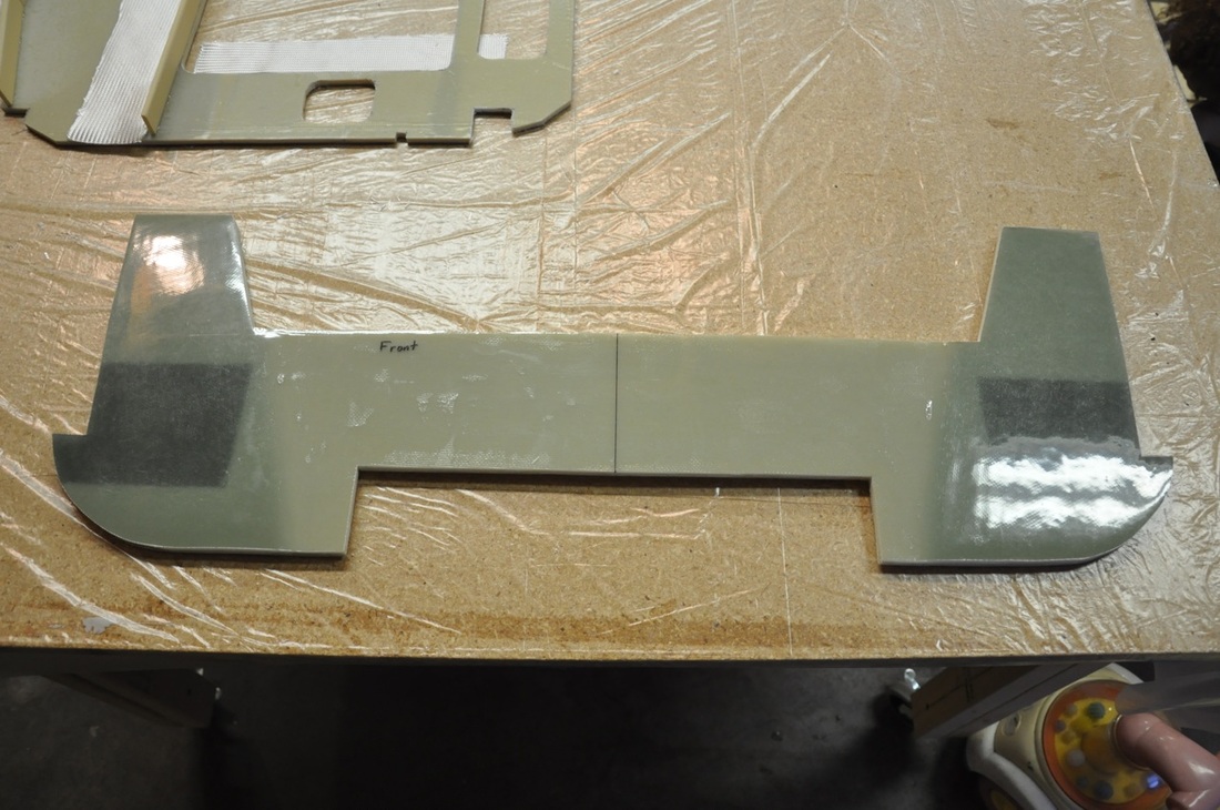
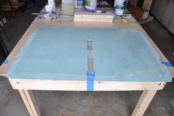
 Hard point installed in bulkheads and ready for glassing
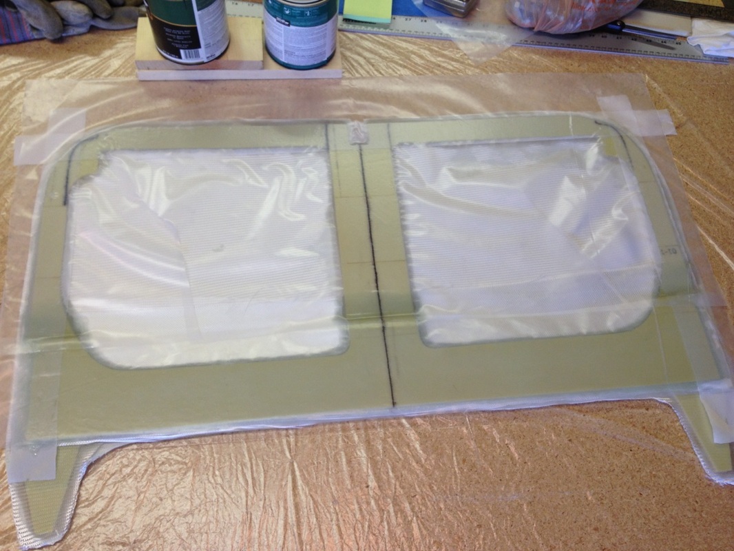
Once glued in place, the bulkheads are ready to be glassed over. These get glassed with BID and UNI over the entire surface. The front bulkhead (both pieces) doesn't receive the reinforcement lay ups until a later chapter. The aft bulkhead gets 8 extra layers of UNI on the sides to reinforce the main gear attachment points. If you're doing a plastic peel ply, I would lay some plastic over the center area where the reinforcements aren't done. This way you don't have to worry about it setting up while working on the sides. I cut a template out of paper to cut the UNI pieces out for the sides so they would match correctly. Remember that the major fibers should run parallel with the slanted sides. Once all layers have been wetted out, plastic was placed on the rest of the lay-up, excess epoxy squeegeed out, then an extra piece of plastic was placed over the entire piece so that a piece of masonite could be put on top without worry of sticking. The masonite was weighed down to keep the piece flat. It was at this point in the construction that I switched plastic from the polyethylene sheets you get at home supply stores to rolls of mylar. The mylar is exceptionally smooth and very transparent making it much easier to see air and other imperfections. You'll see the difference in the finished images below.
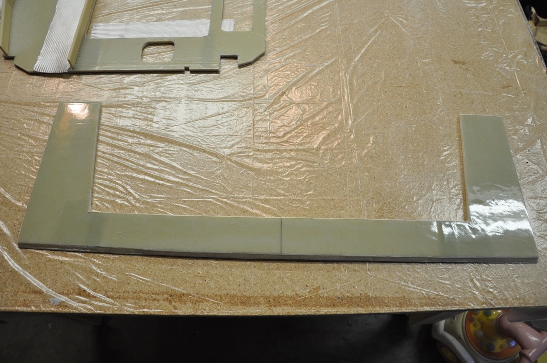
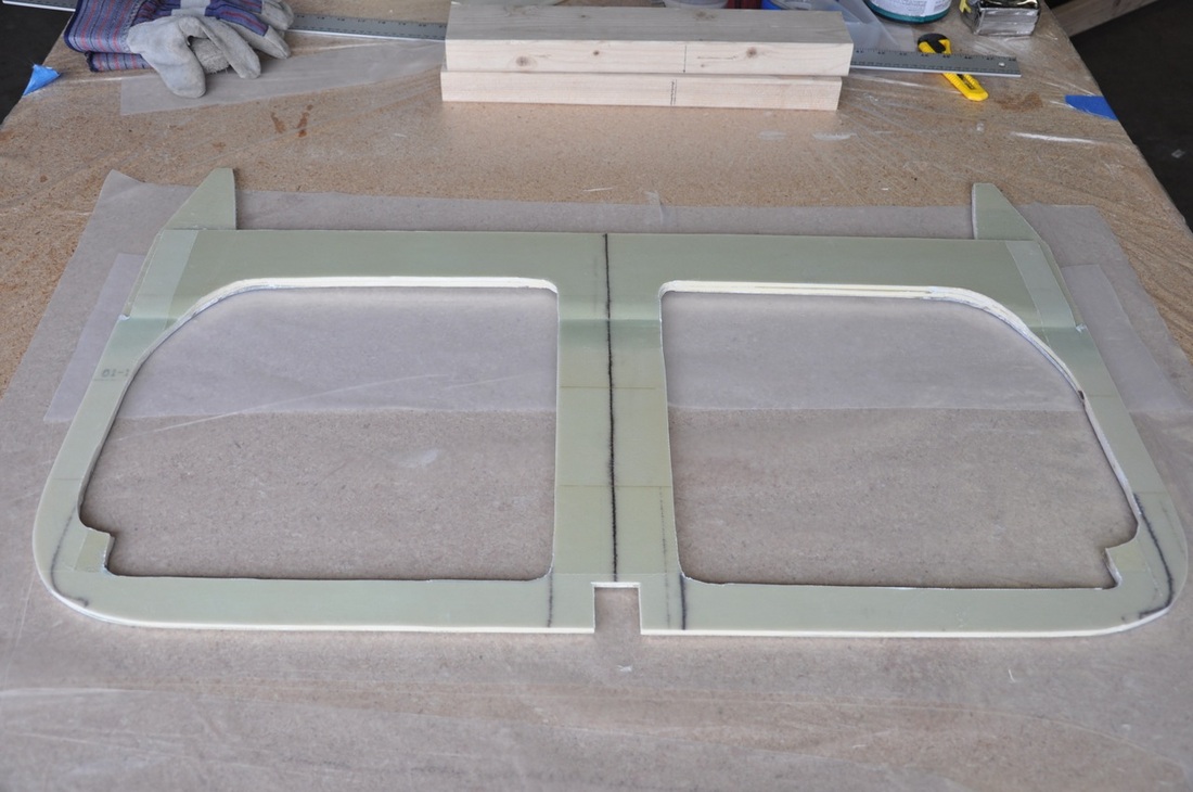
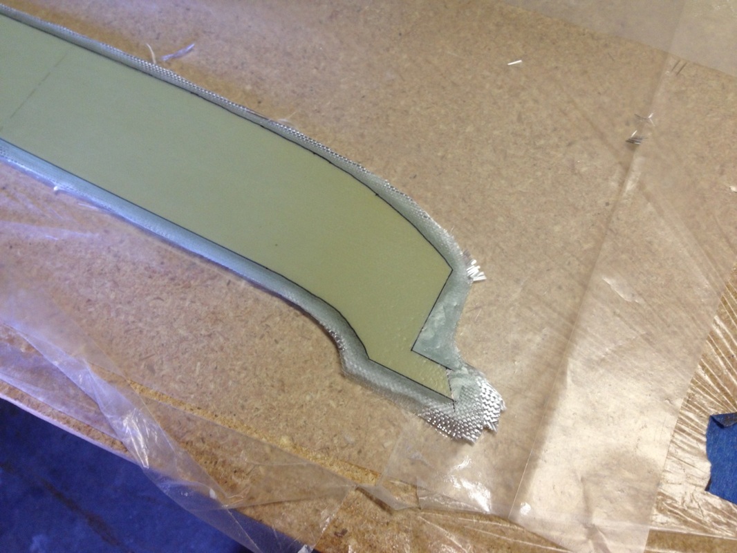
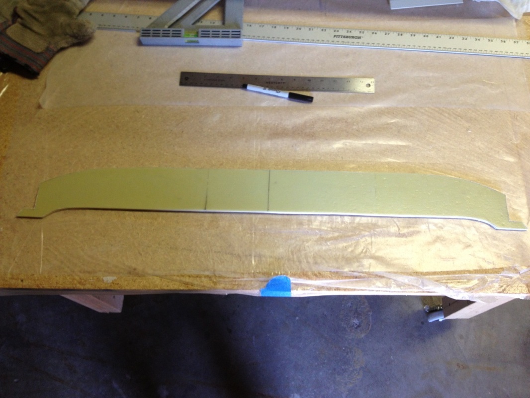
 Forward side of IP ready for installation
The instrument panel (IP) is made in much the same way as the front bulkheads. Several pieces of the foam are glued together to make a single piece (use the hinge method to make it work the best). I made a deviation in the design of the IP by increasing the height of the leg opening and increasing the width by removing material on the outside edge (near the control opening). You don't want to take material from the middle support because it needs to remain the plan thickness for the landing gear pieces. The outside edges were trimmed with a band saw and the inside trimmed using the Fein. Once done, 1" strips of foam were cut in the forms shown on the plans and glued on with 5 min epoxy. These become stiffeners for the IP. They get glassed over with BID. On one side, an amount of glass is curved over the foam and allowed to cure to create a lip that will act as a wire guide. Most builders use tape covered wood to create form for the overhang. Since I know I'm going to replace the IP with a removable one later on, I didn't bother making them perfect. They will be good enough for the construction process though. Make sure to use peel ply or plastic peel ply on the glass layers that are on the flat areas of the IP to make a smooth transition.
After the plastic is removed, parts are checked over for issues. The landing gear bulkheads came out exceptionally well using the new mylar film. I'm waiting to do the firewall till later since several have suggested waiting to cut it once the temporary has been fitted and adjusted during the assembly phase. This made a lot of sense, so I decided to follow the advice. The 0.25 inch holes for the front landing gear bulkhead were drilled in following the written placement of the holes. Don't go by the drawing (at least according to the FAQ). The dimensions given will place the hole in a slightly different position than what's drawn and it seems to be preferable to have it where the dimensions say it should be. Hope it's right.
My firewall templates ended up causing me some headaches. For whatever reason, my drawings had some issues. To start, the centerline on the lower drawing was not perpendicular to the horizontal lines. When I matched the upper firewall picture with the lower one, the center lines didn't match. On top of that, the reference to how far the center was from the NACA scoop read 7.5 inches but measured 7.8 inches. Remembering before that written values were typically better, I went with the shorter one and redrew the center line. This ended up being wrong. What I failed to notice was there was another horizontal reference at the engine mount on the lower drawing. It's 14 inches from the line. A quick check shows the line is very close to this length at that point. So what I did was use that point as the reference position for center and redrew the centerline perpendicular to the top of the lower firewall. For the upper longeron, I made sure the drawings were lined up to the zig zag reference lines in order to keep the placement correct. Hopefully other drawings don't have this issue.
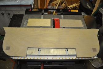
 Temporary firewall cut out and ready.
The temporary firewall was cut out of a 1/4 inch birch plywood piece. Since you only need the longeron holes, there's no reason to make the entire firewall, so I just used a 2 ft x 4 ft sheet. Less expensive and gets the job done. You can see the holes for all the longerons and the conduit area (not necessary, but it does help to line up where the conduit should be on the foam). The actual firewall is made up of four separate pieces and is cut from a 1/4 inch aircraft grade plywood. The stuff is solid, heavy, and made up of 12 layers. Probably the best plywood you will ever deal with unless you're a wood worker. On second thought, a real wood worker doesn't use much plywood...
To trace out the pattern onto the plywood, the same method was used as the foam. The tracing wheel leaves an easy to see mark in the wood just as it did in the foam without committing it to that pattern. If you need to redo, just use another area. I cut mine using the jig saw since there were curves and the internal cutouts. Just drill a big enough hold to get the bit into and the slowly work the area out. I used a fine tooth wood blade to avoid splintering and to leave a fine edge. Worked very well. This was done for both the temporary and the permanent pieces. For the permanent firewall, you can get all four pieces on one 2x4 sheet if following the plans sizes. I know I'm going to increase the back a bit following Jerry Schneider's example. So I'll have to buy another sheet just for the top piece. Nat was real good at maximizing the material usage and any larger doesn't fit on the piece. Oh well. For now I'm just cutting the lower piece and the two side pieces.
To trace out the pattern onto the plywood, the same method was used as the foam. The tracing wheel leaves an easy to see mark in the wood just as it did in the foam without committing it to that pattern. If you need to redo, just use another area. I cut mine using the jig saw since there were curves and the internal cutouts. Just drill a big enough hold to get the bit into and the slowly work the area out. I used a fine tooth wood blade to avoid splintering and to leave a fine edge. Worked very well. This was done for both the temporary and the permanent pieces. For the permanent firewall, you can get all four pieces on one 2x4 sheet if following the plans sizes. I know I'm going to increase the back a bit following Jerry Schneider's example. So I'll have to buy another sheet just for the top piece. Nat was real good at maximizing the material usage and any larger doesn't fit on the piece. Oh well. For now I'm just cutting the lower piece and the two side pieces.
Following the example of several other builders, I made my aluminum inserts 1.25 inches square rather than 1 inch. The extra space allows for any inaccuracies in the mount and gives a bit more wiggle room. Though I'll have to fabricate my own mount, having placement room is always nice. I'm not sure which is heavier: the aluminum or the wood. The lower firewall was cut out of the aircraft grade plywood using a jig saw with a fine scroll blade. The two holes for the aluminum inserts were made as well. I also cut out the two spacers, but used the table saw to get very straight cuts. The upper firewall will wait until the canopy is constructed since I'll be doing a different shape and will need another piece of gold plated plywood (just kidding, though it's expensive). I didn't cut cut the holes for the longerons yet as you're suppose to wait for chapter 6 to see where the temporary holes end up at.
For the aluminum inserts, I decided to alodine the pieces. I ordered both the Alumiprep and Alodine material from Aircraft Spruce (no one in town appeared to carry it). There's lots of debate on whether or not you should do this. Here's my take on the situation:
- You hurt nothing to the part by protecting it
- It aids in adhesion of paint and epoxy (both very good things)
- You can never guess what the material will be exposed to over the years of the life of the craft
- You use very little fluid and as far as I can tell you can reuse the Alodine (the much worse component of the two solutions) thereby limiting environmental impact
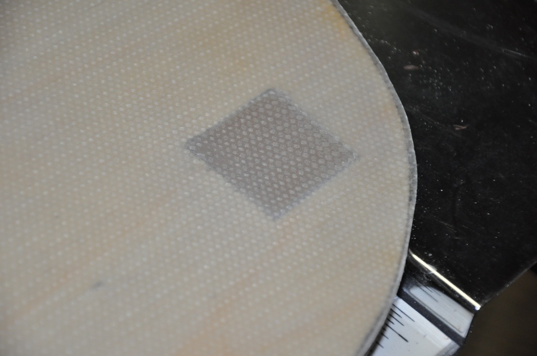
I took the opportunity to use the firewall as a glassing example for another builder that was just getting started. This allowed him to see how the process works and what to expect. So the lower firewall was glassed and plastic peel plied on both sides with 1 ply of BID. The two inserts were used to demonstrate peel ply vs plastic peel ply. Both turned out fine, but you get the rough surface of the peel ply and the very smooth surface of the plastic peel ply and easier to see air removal. I tried to weigh the parts to see if I could tell a difference, but there's not enough material there to detect. A larger piece with more plies would help. I may run a test with scrap if I can get a sensitive enough scale. The two plastic peel ply parts were then sand blasted with 70 grit aluminum oxide to roughen up the surface as a test for the sand blasting method. Turned out very well. They will still be sanded with 36 grit when layup time comes though. With that, this chapter comes to an end. On to the sides!