Chapter 7: Fuselage Exterior
This chapter starts the process of shaping the boxy structure into the hintings of the sleek aircraft that it'll eventually become. First will be the construction of the NACA duct followed by the corner shaping and eventually glassing of the outside.
Tips And Hints
- The plans drawing for the NACA scoop has been shown many times to be highly inaccurate and lacking the full function. The problem comes from not conforming to the guidelines of a NACA scoop. See my build section for info and a new template.
- Extend the foam for the NACA duct most of the way up to the landing brake in order to create a smooth transition. The plan's length will make a dip that will have to be filled later.
- The wooden inserts added to the landing gear bulkheads will likely be different than the patterns. Just trim to fit correctly. The taper will be 45 degree angles.
- When cutting and tapering the foam for the spar cutout, only taper the foam that is on the horizontal cut (along LWY). All vertical cuts should be square.
- Use a belt sander to sand down the lower longeron to the 0.25 inch thickness, then sand the foam to contour.
If you read enough in the archives or in the CAS newsletters, you eventually come across info that talks about the NACA scoop design issues. The problem is that Nat used a pseudo duct layout that doesn't follow the guidelines from NACA papers. This causes the duct to work less efficiently than it should. I did some research and found a great paper that covers the subject which is just distilled from the original NACA papers. The was created by a Glastar builder named Bill Whitehouse. It's readily available on the web, but I have it here for easier finding. I also used an excel file that was distributed at one point that calculates the scoop design and changed it to give the full profile as well as the profile of the lip at the end of the duct. You can use these to find your own duct shape and size, especially if you want to make some for air vents. I used these to calculate the new duct shape that will be used on Serenity. I believe the file will default to my chosen design, but just in case use the following to get the same as me (if you want to be lazy about it): Width: 15 inches Depth: 3.3 inches Ramp Angle: 5 degrees
The important thing is that you want an angle between 4-7 degrees to get the duct to work properly. A shorter duct could be designed with a steeper angle and it would probably work, but since the Cozy was designed with this length and the bottom needs to be flattened out anyway, might as well stick to the original length.
Update:
After making mine I realized there was a step in top part as the duct had not reached the bottom level where it flattens out till after I sanded the bottom to shape. To fix that, the templates below are now resized to extend the duct out to where it should meet up with the bottom. Let me know if there are problems with using the template.
| naca_duct_design.pdf |
| __naca_profile_calculator.xls |
| naca_duct_profile_for_cozy_mk_iv.pdf |
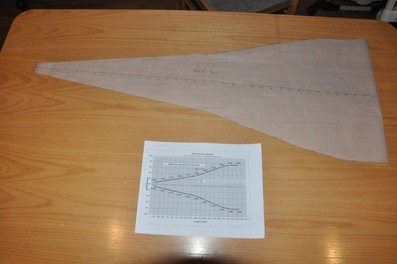
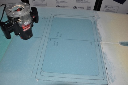
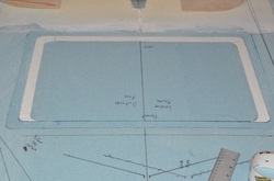
To make my duct template, I took the measurements of the opening at the firewall (15 x 3 inches) and the original duct length of about 38 inches. From this and using the excel calculator above, I was able to come up with a design that was the same length and requires an opening of 15 x 3.3 inches. This should be doable as the firewall opening is slightly more than 3 inches. The slope comes out somewhere between 5 and 6 and is defined by how the bottom was put in. However, this is right where it should be, so it should work out well. Using the printout, I traced onto some tracing paper (same as what was used for the bulkheads) and then cut out. If you had butcher paper, that would probably be better as it's a bit more stiffer, but this should be fine. With the new template, it'll be checked against the bulkhead openings and adjustments will be made as necessary.
The template was laid up on the fuselage matching the centerline. I found that I had to trim the rear landing gear bulkhead cutout which ironically appears to be needed a lot with the original design. Looks like Nat had the profile close to correct except for the front part where it tapers too much. At any rate, the cutouts all matched up just fine except for the one which was easily trimmed with the fein. I didn't have to take off more than a quarter of an inch on both sides. The profile was drawn on the bottom foam for reference.
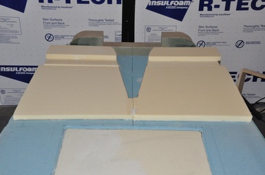
Next urethane foam was stacked on top of the duct area for shaping into the duct. I didn't have 2 inch foam, so I just micro a second 1 inch piece to the top of another. I also followed the advice of extending the foam all the way to where the bottom flattens out (just behind the landing brake an inch or two). This allows a smooth transition to be maintained that won't need to be filled in later. The profile was cut out of the foam just using a utility knife as I didn't have access to a band saw at the time. Worked out fine anyway since this foam cuts soooo easily. Easy to damage as well. Before adhering the urethane to the bottom, supports were added underneath to keep the bottom from sagging when the foam was weighed down. To weigh down the blocks, I made sure to add something flat to the surface to spread the weight out and not deform the foam (remember, very soft stuff).
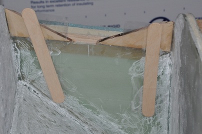
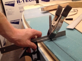
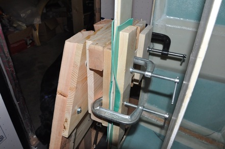
Next came the wooden inserts used to make supports for the foam around the landing gear bulkheads. I traced the images as shown then copied them over to the leftover firewall wood using the tracing wheel, but as with most other builders I had to modify them to get them to fit. The widths were fine, but the angle was off. I used the spot where the piece meets the curve the bulkhead to mark the trim location. Remember that these get attached flush with the interior wall. The tapered areas are suppose to follow the curve of the bulkheads, so that's what I used to find my trim locations. Minor trimming and they were able to fit okay. The taper is just a 45 degree angle (as best as I could tell), so I set the table saw to a 45 angle cut to do the tapers once I got the pieces sized for the location. I then followed Bernard Siu's example of using mixing sticks to help support the pieces rather than nails. Don't forget that the wood inserts are opposites on each side, so it's best to do the taper once you fit the piece, then you can mark the correct side for the taper. For part D, I made sure it was level from left to right. I used clamps to help hold the pieces between the firewall and aft landing gear bulkhead tight against the sides for cure. Any gaps were filled with flox.
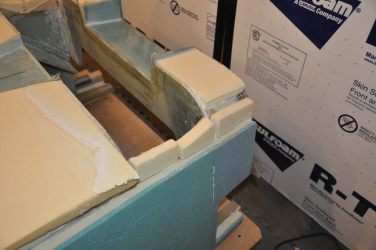
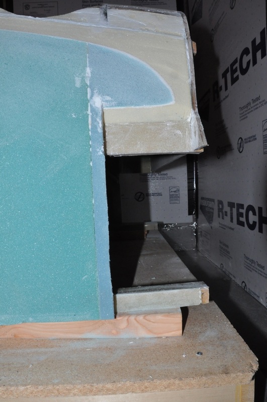
Urethane foam is added to the inserts to be used for shaping the contours later. For the triangular pieces, I used pieces from the NACA duct cutout which were triangular to begin with. So instead of using one rectangular piece, I went ahead and used two pieces for each side. They will be sanded down to the same shape as the wood inserts later on anyway. These were attached with just micro. The foam that went on the large wood spacers was attached with micro on top of 2 ply BID that was added at the same time. Really hard to get the BID to stay in place while trying to place the blocks. I probably should have waited till the BID tacked up, but I didn't have the time to wait. I got it in with a small amount of disturbing. After cure, the foam and glass was trimmed on the inside area for the 3/8 inch PVC foam.
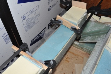
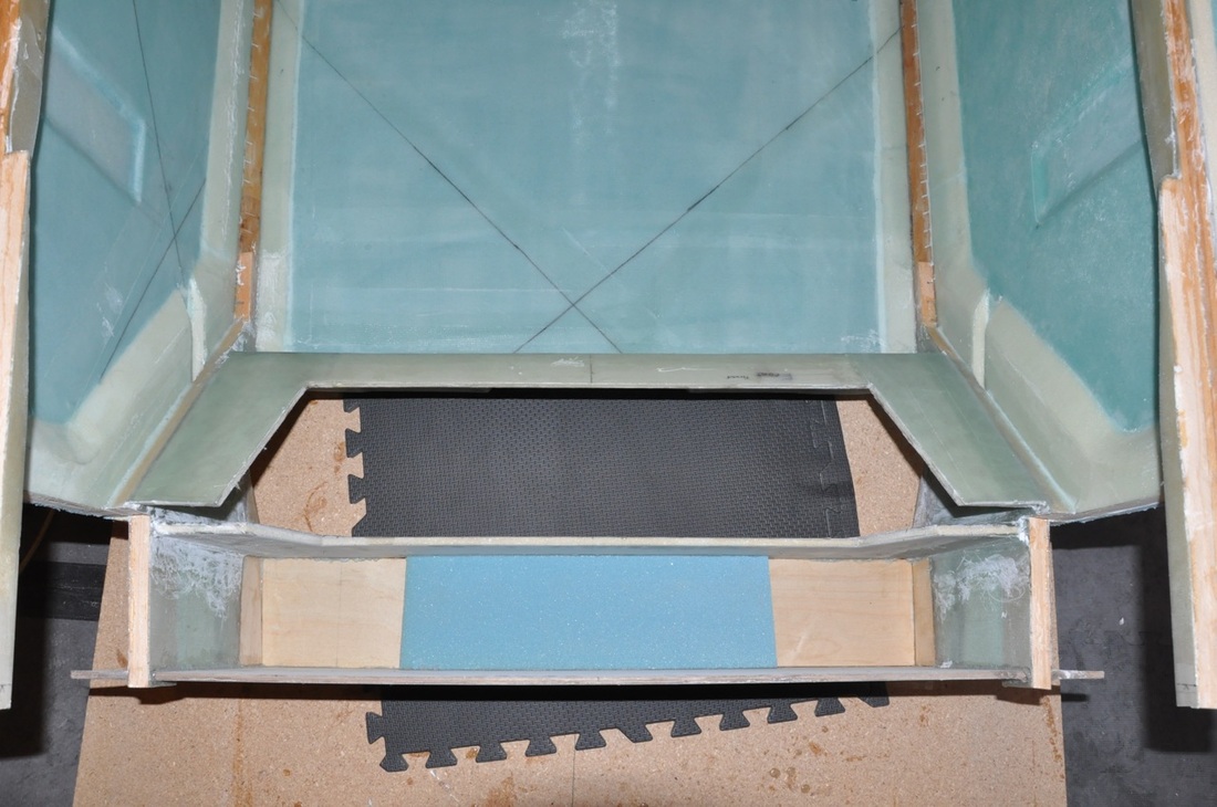
3/8" PVC is used to close up the space between the aft landing gear and the firewall. This makes up the end of the NACA duct and creates the bottom of what gets affectionately called the hell hole. Since I'm not doing the joggles for the landing gear cover, I made everything flush. The long piece that goes across the middle was cut so the sides were angled so they would sit flush with the bulkheads (One side is higher than the other. This gave a tighter fit that allowed me to position without using nails. The side pieces were trimmed to fit the profile of the opening. Once fitted, these were floxed into place. The sides I held in position with clamps as they did not fit as snug as the bottom.
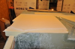
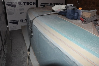
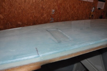
Next came time to sand the NACA duct down. I followed the plans and just glued 36 grit belt sand paper to a 2x4 to accomplish the task. I placed a piece of packing tape in front of the foam to protect the PVC foam bottom as I got close to flush. The urethane sands easily, but it's still hard work. I stopped occasionally to vacuum up dust to keep the mess at a minimum and check on the progress. I made the board long enough so that it would reach from the bulkhead bottom to the flat area by the landing brake. In theory, you can't sand too far doing this because you can't go past your sanding level. I did sand the foam level with the bulkhead as I plan to do Wayne Hick's landing gear cover idea.
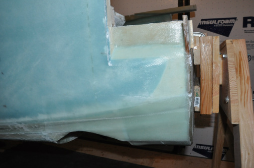
I also sanded the end of the blue foam within the duct to help get a smoother transition to the bulkhead. Once sanded and checked for levelness, the inside of the scoop was glassed over with 2 ply BID. Micro was added to all the glassing surfaces and the bulkheads were roughened and the corner rounded where needed to wrap around. Dry micro was added to the corners to round out the transition for the glass. I found that I had to add dry micro to the front of the scoop to help transition it to the bottom since the foam was extended forward to get completely flush. If you did the plans length, it would end at the foam. Considering the alternative was to put micro all across the bottom to smooth it out, this was a minor detail. It takes a gentle hand to micro the surface of the urethane foam as it tends to crumble as you spread it onto the surface. Templates were made for the glass and the same method for BID tape was used to put the fiberglass in place. Apparently, I didn't round over the corners enough and had several difficulties with getting the glass to lay down. I can see now how those joggles would've been a major issue. After wrestling with it awhile, it appeared to stay in place. I put plastic over most of the surface, squeezed out excess epoxy and air, and left to cure overnight.
Well, so much for staying in place. I ended up having a large bubble area at the end of the duct at the front landing gear bulkhead. I'm pretty sure what happened was that because the temp in the room was above 80 (I hadn't gotten a AC unit in place yet) and because I thought a small layup like this wouldn't be a problem, my micro layer on the foam hardened up past the point of assisting with adhesion with the glass. It only lifted where I had sanded the foam and had to use extra micro to fill in the gaps (you can see the whiter area in the glassed scoop image). So time for more learning. First I trimmed the excess glass so it wasn't in the way. Just to make the repair easier, I decided to just go straight across and remove the entire area. I once again used a angle grinder with a 120 grit sanding disk to taper the glass, then followed the repair procedures. Other than that, everything worked out well.
I also had the same issue along the wood of the firewall and along the aft landing gear bulkhead edge. So I had to cut these out and glass back over. Sigh.... Oh well, better to fix it than be done with issues.
I also had the same issue along the wood of the firewall and along the aft landing gear bulkhead edge. So I had to cut these out and glass back over. Sigh.... Oh well, better to fix it than be done with issues.
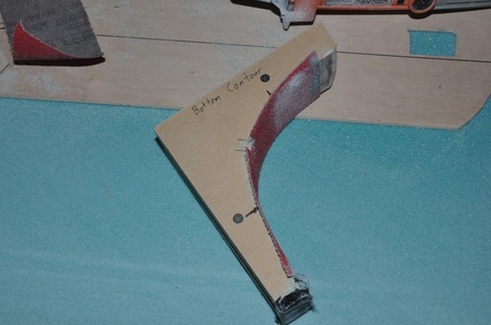
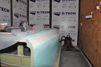
So now comes the big moment where you start to see the slick contours of a canard aircraft. You now get to shape the corners from a square look to a rounded look. Before you get to do that, you need to make your contouring blocks. I chose to cut mine out of MDF mostly because this material cuts cleanly, is nice and solid and flat, and sands easily to shape. Using the templates in the M-drawings, I traced out the profiles and used the fabric rotary tracer to lay a dotted line path to follow. This was thin traced over to make it easier to see and cut out. I had to use my jig saw to cut as the band saw was not available. The band saw would have done a better job, so I recommend cutting that way. What I did to get a big enough block was to cut the first one out of 3/4" MDF and shape to be as accurate as possible. Then I rough cut the others slightly oversized and attached it to the shaped one and used a flush trim router bit to trim to shape using the original as the guide. This works very well for most of the templates except for where there's the sharp corners on the Upper sanding blocks. Those will have to be trimmed manually for each. My final blocks were three pieces of 3/4" MDF screwed together to give enough thickness to glue a belt sander strip to it. The belt will hang off some, so if that bothers you, you can add a fourth piece or trim the belt. For the lower edge template, I used this overhang to cut a notch out where the lower longeron was suppose to be to use as a guide for sanding.
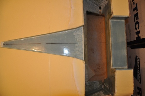
This is the section that so many have been tripped up on by the instructions. The updated instructions talk about imagining a hot wire being used to cut the foam (don't actually use a hot wire, this foam is hazardous to cut with a hot wire) along the back side where the wire is attached to a point 25 inches from the firewall at the lower longeron and then follows the firewall profile. Two problems develop from this: One is that there's no mention as to what height you should assume the pivot point reference is taken from the lower longeron, Two is that if you sand too much you risk exposing the electrical conduit. The other confusion comes from how to taper the foam. After researching and asking others, I believe I got the correct answer and hope I won't be adding an update saying I was wrong. So here we go. For the side tapering, I glued 36 grit sanding belt to a straight 2x4. I then used it to sand along the side with one end going through the pivot area. Wanting to avoid exposing the electrical duct and realizing that this was mostly a cosmetic change, I chose to round the taper more than keep it straight. Using the firewall as a guide, I sanded the foam at a high angle so only the foam at the back was sanded. As it rounded off, I then lowered the angle so now I was sanding the foam away from the firewall. I kept working in this fashion till the foam was rounded all the way to the 25 inch point. I never exposed the duct and the rounded shape looks really good and aerodynamic.
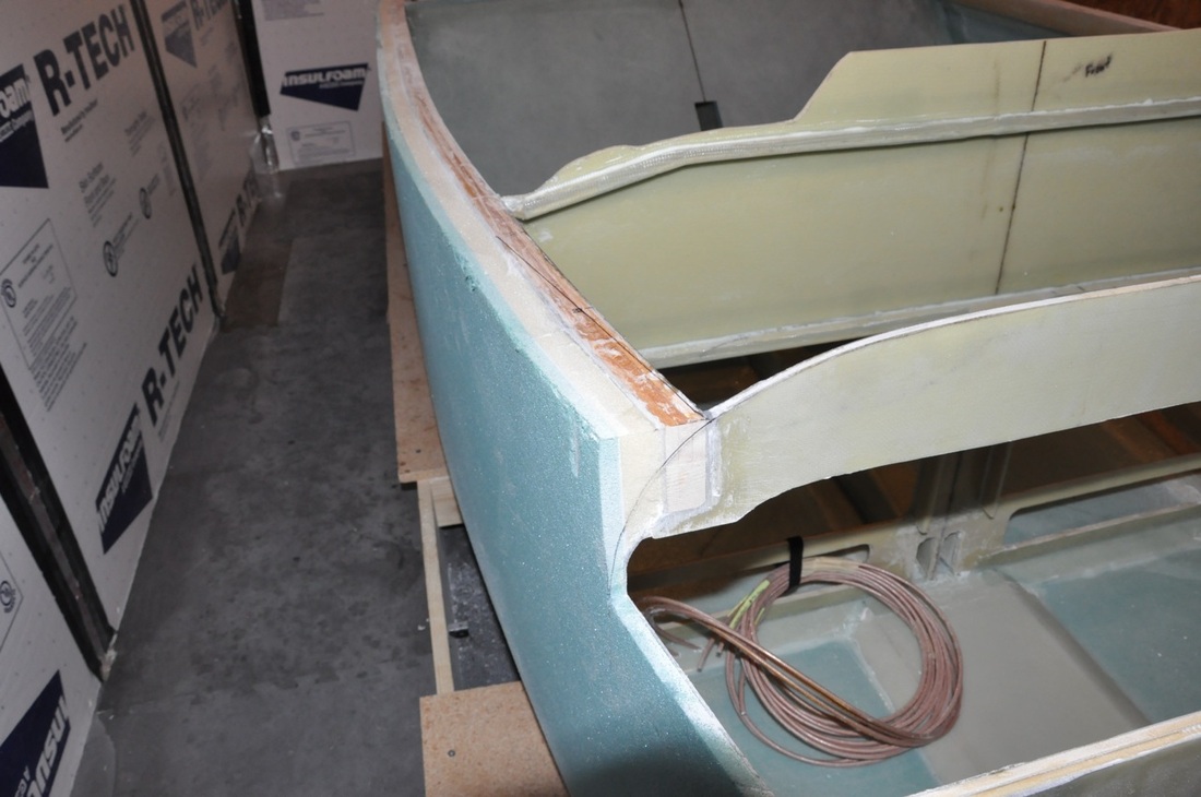
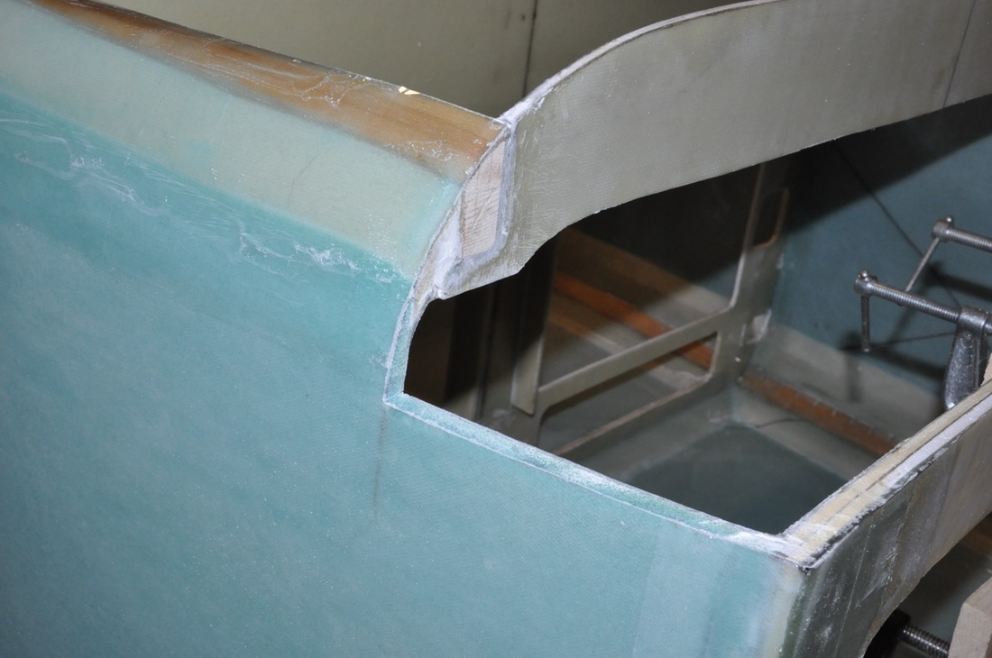
To cut the foam out for the spar area, I used the fein tool to cut under the foam and along the vertical line. For the tapered area, I also used the fein to cut at a 45 degree angle, then sanded the edge to round it out for future glass work. Here's the important part that gets a lot of people. There's questions as to what gets tapered. To the best of my knowledge and research, you ONLY taper the HORIZONTAL cut along LWY. All vertical cuts of foam, even if over LWY and the upper longeron, remain square. the reason for the taper is that the spar gets attached directly to the wood for strong support. The upper longeron doesn't have foam on it in this area so there's no tapering. The forward edge, however, doesn't provide the same type of support. (UPDATE: I was wrong here, maybe. It appears no one really knows what's happening. At the very least, the foam in direct contact with LWY and the upper longeron should be tapered down to the surface. The rest is questionable whether it should be or not. Considering the multitude of ways that this has been done, it probably doesn't matter much. However, to make up for my issue, I did hadd a couple of plies of UNI to go from the wood onto the side to at least connect the two areas I didn't taper. May not be necessary but I would rather be safe than sorry) If you taper the vertical cut, it will end up as a depression later on when the spar is attached and it will have to be filled in. (I do hope I'm right on this). You only need to remove the foam. The glass and flox layers should be left behind as far as I know. Sand off any remaining foam from these areas to prep it for future layups.
UPDATE 2: After looking this over, I think leaving mine the way it is will be fine. However, I would round off the corner so that the glass can be layed over onto the wood and the exposed foam side along the cut edge. You could slope the foam around the wood as well. Either way works.
Now to start tackling the corners. First thing, guide lines should be drawn to show where the foam can be cut. Using a jig saw or hack saw, cut at a 45 degree angle to remove the majority of the foam excess to make the foam cutting go quicker. Though the foam sanding goes slower than you would expect (especially the PVC foam), what really slows you down is micro, glass, and flox. The more of this you can remove, the faster it'll go. Using some right triangle math, I found where I should cut at to get close to removing up to the 0.25 inch of lower longeron called out in the plans. However, this didn't work as well as I had hoped. I drew a line by clamping a pen to the correct location on a square then laying the guide line down on the foam both on the bottom and the side. The jig saw was fitted with a long cutting blade and set to 45 degree angle and then ran along this line. What ended up happening was that the blade would flex to much when it encountered the harder material and I was not able to cut the lower longeron. However, I feel that you don't really need to and there's a better way. So I went ahead and removed the foam at a 45 degree angle all the way back.
Now to make things easier. Once the foam is cut back, you want to expose 0.25" of thickness in the lower longeron. The easiest way to do this is to use a belt sander with a 36 grit belt and go back and forth sanding at a 45 degree angle (or flat to the cut you just made) and constantly check the wood to see if you have reached the thickness. Don't stay in one spot, but move along the length to ensure you get an even cut. Once an area is at the right width, move on and don't go back to it. Now, those that paid more attention to the plans realized that the lower longeron was only suppose to expose a quarter inch up to the middle of the landing brake then taper off from there. I somehow missed that and did it past the landing brake (mostly to where the NACA scoop starts). This apparently has happened before and is just a cosmetic issue. Looks like the biggest issue is that it will be harder to round out the back without a flat spot, but I think it's a minor problem.
I didn't do the secondary cut talked about in the plans. I felt the belt sander would do a better job as long as I didn't go too far with it. Actually, what I ended up doing was cutting a sanding belt in half (36 grit), then holding it between both my hands I sanded across the corner at a 45 degree angle doing a "shoe shiner" type move. This sanded the high points on the edges and started to bring them towards the lower longeron. Once at the lower longeron, the flox wouldn't allow the belt to sand much past the lower longeron and the sides started to round out. Again, I didn't sand in one area but moved along. I would sand some, stop and use the contour template to check for high spots, then reverse the sanding direction (90 degress to the original sanding orientation) and go back over the high spots. Once I was really close to the contour template shape, I used the template with sand paper glued to it to get the final shape. This created a fairly uniform contour across the edge. I used this contour to about where the NACA duct starts, then I had to round without a template due to the thickness changes. This is an artist moment as there's no one way to do it, so sand to a "pleasing shape" to blend in the transition. To sand the other side to the same shape, I used the width of the urethane foam band as a guide on how far to sand. Worked out very well.
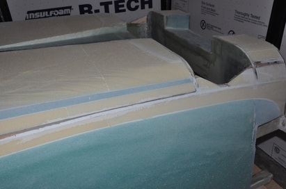
Most likely, you will find as most other builders have that there will be a gap between the foam right along the NACA scoop - landing gear bulkhead area. The way the foam is layed out, it's pretty much inevitable that there will be a gap because the foam doesn't overlap any during the assembly. Some fill with foam, some with micro. I chose the micro route because my gap was fairly small and foam would have been difficult to shape to fit correctly in it and wouldn't necessarily have been lighter than dry micro. So I mixed up dry micro, vacuumed the area clean of dust, and used the sandwich bag piping method to apply micro in any gaps. This was carefully smoothed out flush with a squeegee. It was then lightly sanded to clean up any rough edges. That faired in well, so now onto the next thing!
Now that the sides and back have been contoured, attention can be spent on making the required 1/16" depressions for glass transitions. The first was an area around the landing brake. There is a 2 inch wide area for the sides and aft edges of the brake and a 1 inch wide area for the forward edge. I chose to round my corners using a wooden dowel for the profile. I have seen some remain square and it would probably be fine, but I prefer to have a softer edge. To remove the foam, I set my router to 1/6" depth then routed out the foam. Very easy and leaves a good profile.
Next is the 1/16" depression along the front edge. I again chose to do the router though this proved problematic. For starters, the area here isn't flat. There's a slight slope. There's also no support on the other side, so you rely on a single side of support. Doing it again, I might opt for the belt sander, but I was able to get my depression. Your mileage may vary.
There's a 1 inch border around the landing brake that must be built up. I chose to use 3M double sided foam tape. This comes in a role that's 1 inch in width and is 1/16" thick (or very close to it). I used scissors to cut the different corners I needed and layed it out around the brake area. Once the tape was down, I covered the top with clear packing tape and overlapped into the brake cutout area. This will be under the landing brake foam and will help keep the brake sticking from any epoxy that runs down the gap (hopefully). Once everything was in place, the brake was glued down with tiny dabs of 5 min epoxy and the brake placed down with weight to make it flush with the surface.
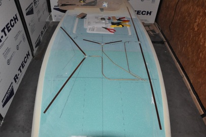
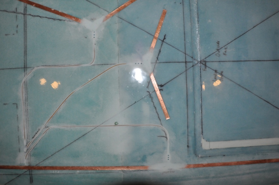
Next it was time for the antenna layout. There doesn't appear to be any standard way, so I followed what some people have done and put three on the bottom: Glide Slope, Marker Beacon, and a Nav antenna. Following the instructions in RST info, the really important items are keeping the tips away from large metal objects (a bit harder to do than said), exiting the coax at a 90 degree angle, and keeping the dipoles at a 10 - 30 degree orientation to a reference plane except for the marker beacon. Apparently the marker beacon may become obsolete soon, but I decided it wouldn't hurt much to put it in. I don't know if I got the coax to run straight out for long enough either, but again it may not matter. We'll hope it works. While I was at it, I wrote down the coordinates for both ends of the antenna strips so that I could pinpoint their location later on when I can no longer see it. Don't know if it'll be useful, but it couldn't hurt to know.
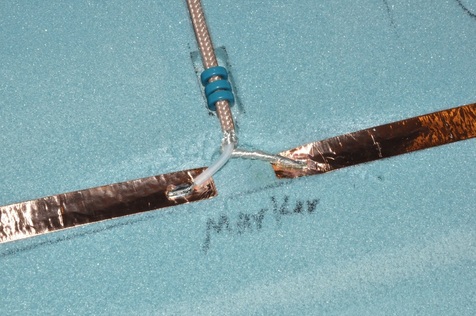
I drew out lines for the dipoles and did a few iterations till I found a setup I liked. Again, it's probably not the most perfect layout, but it's what I'll have. I put the Nav antenna pointing to the side to fit the area. This will be a backup antenna (the main one will be in the canard) and should still function just fine. I targeted 20 degrees of bend to put it in the middle of the range, but the Nav needed about 25 to fit. The wire from the Marker beacon ended up getting close to the Glideslope because I was trying to avoid getting the marker tips close to future metal objects, but hopefully it doesn't interfere. There's no guarantee that these will even be of use in the future, but they're in place now. Once the locations were decided, the wire routes were routed out using a 1/8" router bit set to route out above the foam about 1/8". I should have set it a bit lower as I had a problem getting the wire to sit inside the channel when I microed it in place. For the connection areas, I sanded a small ramp out to bury the solder connection and routed the foam out for the torroids. Since they are the same thickness as the foam, you have to sand the area as far as possible to the glass in order to get them to sit flush. Some of mine were still just slightly above the surface, but faired in with micro later on. The copper foil was cut to specifications and laid out onto vacuumed foam. Once soldered, the connections were checked to make sure there was continuity between the foil and wire, foil to end of wire, and no cross connections. All checked out fine and the solder joints were solid. The wires were brought in on the forward side the IP at an angle along the bottom of the passenger area. I didn't want to bring them up through the heat vent area because I didn't want to heat the wire or block the flow. I plan to put a fairing in to smooth the floor from the IP edge to the floor so it'll serve as a wire cover and a smoothing cover so you don't catch the IP getting in and out. Hope this doesn't cause an issue in the future.
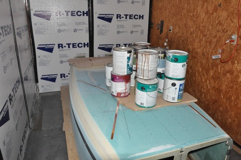
Once the connections were made and everything was in place, everything was microed in place to fill in the gaps, lock it in place, and level the surface. I used Peel ply on top of the micro to keep a rough surface for future lay ups and then covered it with plastic and flat boards and weights to hold everything in as well as possible. In the end, the only problem I had was in an area with the fuselage bottom had no support so it sagged a bit creating a low spot. This will just have to be leveled off later.
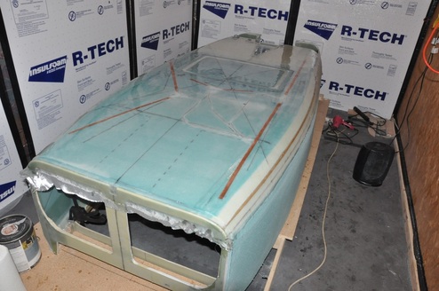
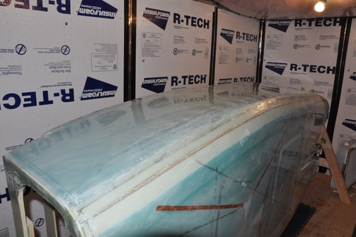
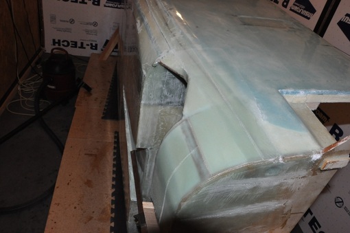
So now comes time to do the large bottom layup. To prep, the fuselage was leveled as best as possible then clamped in place. I drew a line one inch below the lower longeron and another line 2 inchs below the lower longeron. This marks the two places to end the glass at. The first layer will go to the 2 inch line and the second layer will go to the one inch line. This allows the side layups to overlap without creating a large bump in the layup. The area was sanded slightly to help avoid a bump as some mentioned this was a good idea. However, in my case, I think I made it worse and should have left it alone. Oh well. It'll have to be fixed later on now. For this layup, I had to get help, so my friend Dan came to the rescue. I had the glass cut and marked for all the layups, so we got to micro application then wetting out glass making sure to place the UNI at 30 degrees along the guide lines. After the two layers were put on, there are re-enforcements that are placed over the landing gear and engine mount areas. Then the entire surface was covered with mylar and squeegeed to remove air and excess epoxy. In my tiredness, I forgot to end the second layer at the one inch line. This may work in my favor since the sanding depressed the area too much, so this will help build it up. The layup turned out well with only some minor bubbles that had to be filled.
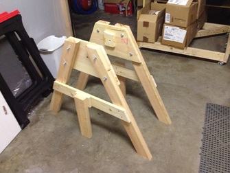
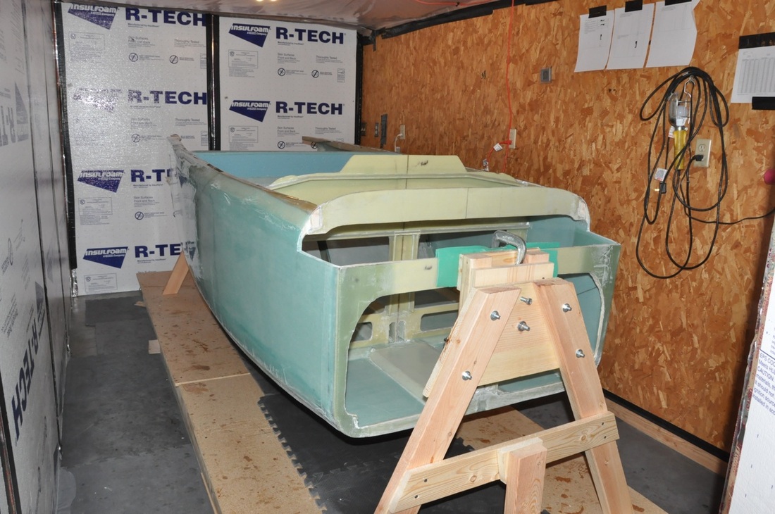
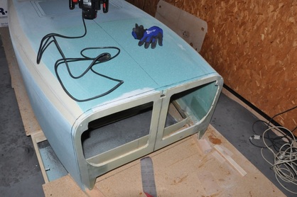
After trimming away all the excess fabric and doing a few bubble repair, it was time to move on to building the rotisserie stands. These are used to hold the fuselage on both ends and allow positioning for layups on the sides and for some of the work inside the fuselage in Chapter 8. the plans gives a rather basic explanation of how to build one (really, just an image) and talks about drilling holes through bulkheads to bolt to. I followed others and made a clamping style block. This allowed me to play with the position to get it in the right spot and didn't create repairs down the road.
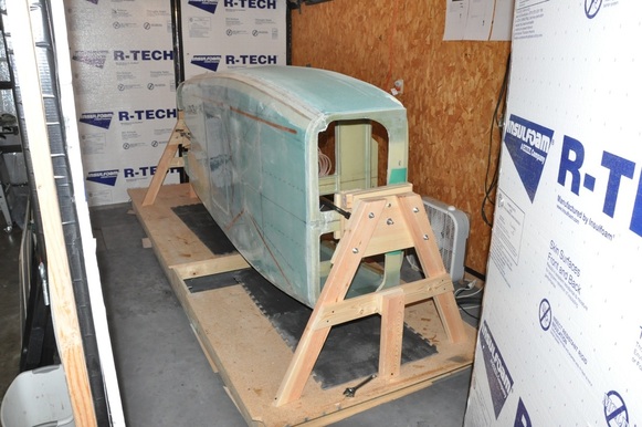
To make the stands, I cut out 2x4 legs at about a 30 degree angle. I used a 1 x 10 as a base plate to attach the legs and make the pivot point. The pivot was simply a 3/8 inch bolt with 3/8" ID plastic tubing around the threading to act as a bushing. I them used various wood parts to make the clamping blocks to fit the two different areas. Another 3/8" bolt was used to pin the rotation on both sides when at the desired angle. I screwed the legs down to the table to avoid any movement of the stand and periodically check the clamping pressure. This turned out very well.
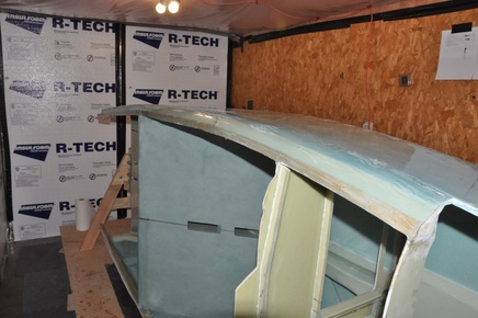
It took a little bit of thought on how to get it on the stands by myself, but I was able to and was rewarded with a 360 degree rotating fuselage! I made pin-off points for the four main orientations for later use. So now we're ready for the side glassing.
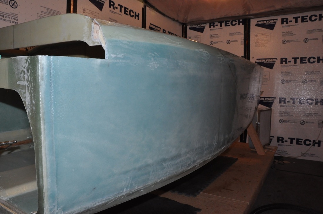
To prep for the side layup, I turned it with the side facing up and drew 30 degree guidelines in order to find the angle easier when laying out the glass. I also remarked the overlap lines for easier viewing. I then taped up plastic to protect the inside and bottom surfaces from drips of epoxy that are inevitable. UNI cloth was cut out for the layup and tagged (2 ply at alternating 30 degrees from longerons, 1 ply parallel to longerons, and re-enforcement pieces across the longerons and at the rear engine mount). I had to sand the lower landing gear area for the re-enforcement layup since the plans didn't mention peel plying this area. If you're not there yet, peel ply this for easier work down the line.
So the big layup came! With the help of my friend Max, we took about five hours to do the full layup. The three UNI plys went as expected. I ran the 3rd ply just above the overlap area as mentioned in the plans. The three strips of UNI across the longeron were a bit difficult. I decided to just lay them out without the plastic since the only long area I had to use was the floor and didn't feel like working on the floor at the time. As you expect, you get the UNI stringies a lot working this way even when using the taped edge (because you eventually have to cut those off). After a bit of fighting and wrestling, we did managed to get them in place. I then plastic plied the entire area and removed as much epoxy and air as I could without making other problems occur.
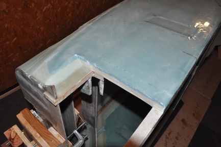
One place of interest was the area at the spar cutout. The plans doesn't really cover what to do here. Looking it over, I realize that the exposed wood at the bottom of the cutout already has fiberglass on it, so it would make sense to go ahead to extend the glass onto it. So for the glass that was on the square cut foam I just trimmed to the edge. For the glass that was over the tapered foam and the wood that it tapers down to I just cut the foam along the taper and the front part of the spar cutout till they met, then the piece just lays down within the tapered area. It's a mouthful to say, but rather easy. Hopefully the picture makes sense.
The engine re-enforcement layup was a bit odd because the picture shows one thing, but when you look at it in person it appears to be another. In order to get the layup to sit right, you have to angle the pieces a bit. This has to do with the curve of the corner. I made up the three plies on plastic by the BID tape method, cut to size, then took to the area and tried to fit the area over the engine mount so that there was equal length of glass around the aluminum square, then ran the glass along the side just below the opening for the landing gear so that there's full adhesion with the side. This seemed to work fine, but it's not what's in the picture. After pressing it in place and working out the air, the area was covered with 1 ply BID. I had to really distort the fibers to get the piece to lay in place (don't know how you couldn't considering the number of different curves to accommodate). Once done, the entire area was peel plied as per the plans. I'm trying out the pinked peel ply and will see how it does in terms of leftover strands. The entire layup was left to cure.
After cure, I was rewarded with minimal issues. There was one bubble up front where there was a slight depression at F22 that the glass didn't want to sit in. This was just filled. There were only a few 1/4 -1/2 inch bubbles in a a few places, but very minimal and not worth fixing. Again, it won't be perfect, but it's okay per the inspection criteria of the plans. The plastic did a great job of smoothing things out. There were some thicker epoxy areas where the plastic puckered a bit. I shaved these areas down some with a finger planer to aid in finishing work down the road. I was so excited that I decided to have some fun with the rotisserie and made the following GIF file:
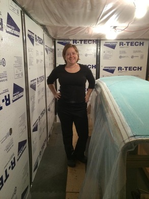
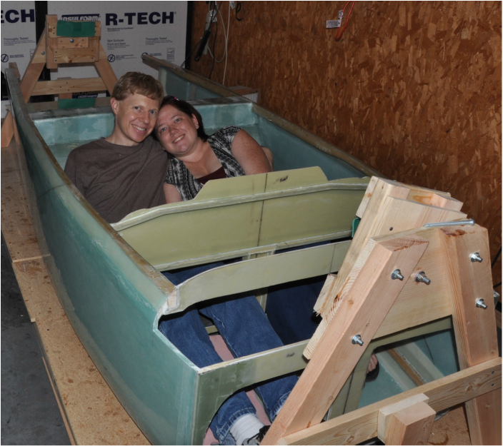
With the rotisserie fun out of the way, the plane was then prepped for the last layup of the chapter: the other side. This will complete the fuselage build and will mark the point where we can first sit INSIDE our project. The plans tell you not to, but some foam padding is all that is needed to really inspire yourself to continue. Alyssa was able to help with this one. Ironically, the last time she was able to help was when we glass the other side of the sides. It was only fitting to bring it full circle.
Glassing was carried out much the same way that it was previously. The only change was that this time I did the BID tape method on the longeron layup. This definitely kept the stringy mess down and possibly cut down the amount of time to do it (you can wet all three layers at one time this way). It was a bit awkward working with a long piece of glass sandwiched between plastic, but we managed to get it to work.
After all glassing was done and areas were peel plied where needed, the entire area was plastic peel plied to remove air, smooth out the surface, and remove as much excess epoxy as possible. This was left to cure overnight. Upon inspection, there were only one bubble needing repair (on F22 at the corner again! Can't catch a break with these corners!). Using the fein tool, all the excess was trimmed off. Any high spots from stringies were sanded down and the peel ply threads were removed. I started using the pinked peel ply fabric. It's much better about not unraveling, but it still leaves behind some strands, they're just little triangles now. An easy way I found to remove them was to use 36 grit sandpapper over the surface where they were, get it roughened up some, then scrape a razor blade over the area and they seem to just come right out. A pick is also handy to have when peel ply gets stuck under epoxy.
So finally the moment has arrived. The fuselage is glassed inside and out, the edges have been trimmed, the dust vacuumed out, and it's been laid out onto foam padding for protection. Ironically, we close this chapter on the first day of Rough River, so we're flying there in spirit. Oh, and yes, we made airplane noises. On to the next chapter!