Chapter 12: Canard Installation
With the wing and elevators made, now's the time to install it on the fuselage! It'll be the first thing to make this look like an actual plane. This should be a fairly short chapter, but one that needs lots of measurements done.
Special Tools Needed
- Drill guide for tubing (ACS #12-02937 or equivalent).
- #10 drill bit
- Self-leveling laser line
Tips And Hints
- If you check or canard and find that there is some incidence change across the span, it's been known to happen (happened to me). Averaging out the noise, I had roughly half of a degree of twist. Some have had almost 1 degree of twist. They're flying this way. Moral of the story, don't sweat it.
- I decided to try to split the difference when setting the incidence, but I leaned more towards the leading edge up as down is worse.
- A self leveling laser helps with the alignment.
- In order to make removable alignment tab pins, you will need 3/16 inch ID aluminum tubing, a #10 drill bit, two K1000-3 nutplates and rivets to match, and long AN3 bolts (AN3-40 to AN3-42 depending on your build).
- An easy way to fill the gap between the canard and the fuselage is to tape up the torque tube enough to make a 0.1 inch thickness around it, add tape to the fuselage, then use spray foam or expanding foam to fill the gap. Trim and glass over after the foam cures. Expanding foam would be better as it makes a more sandable material but will take some planning to keep it in place.
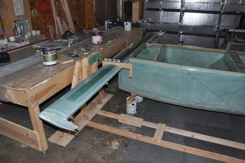
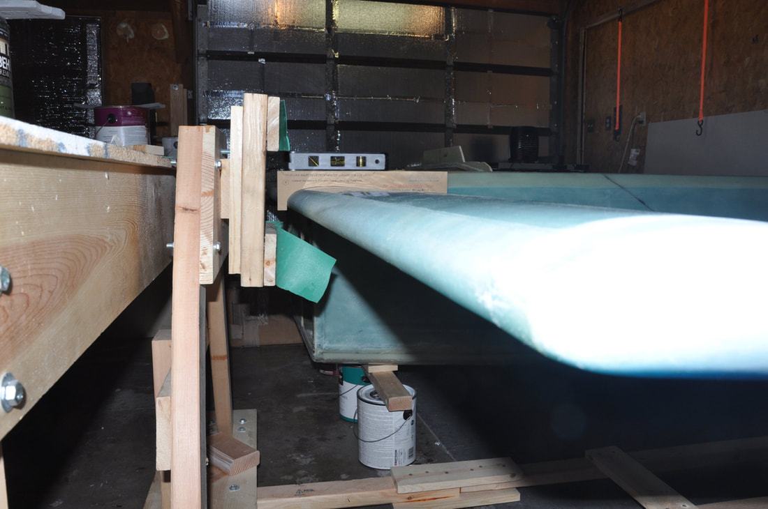
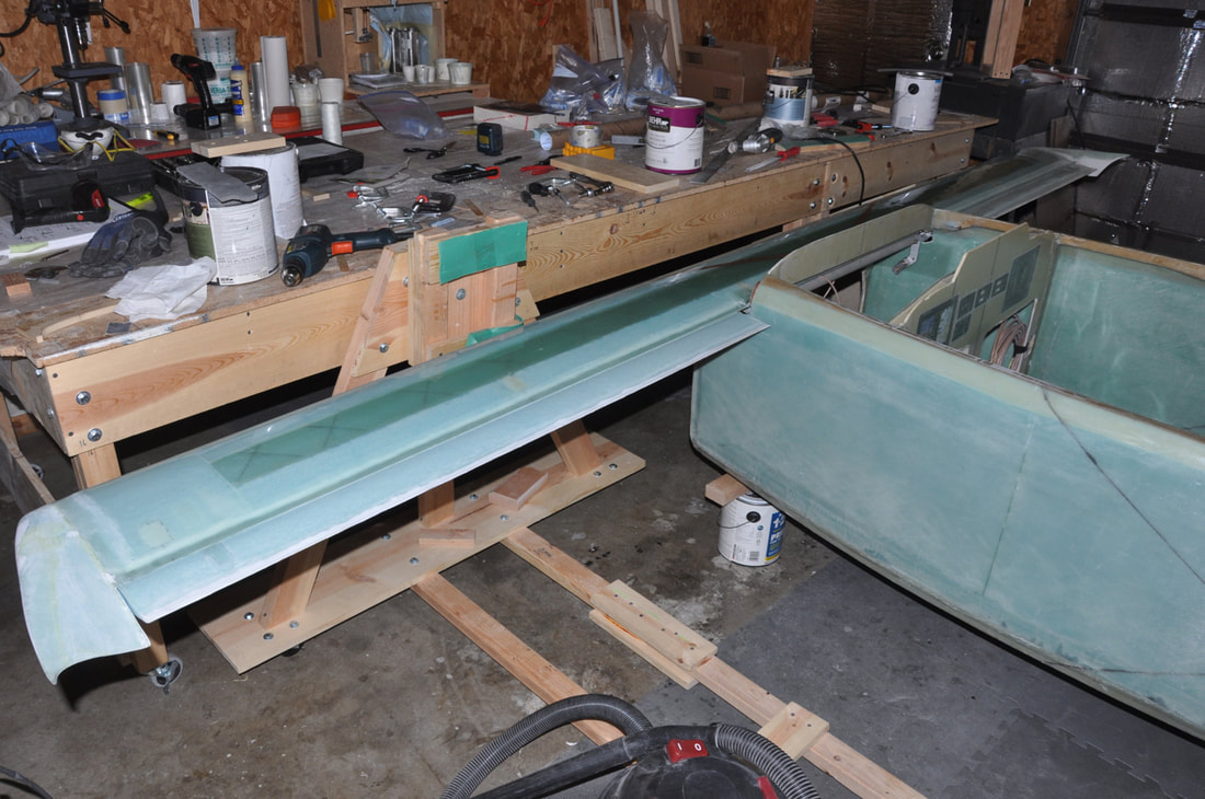
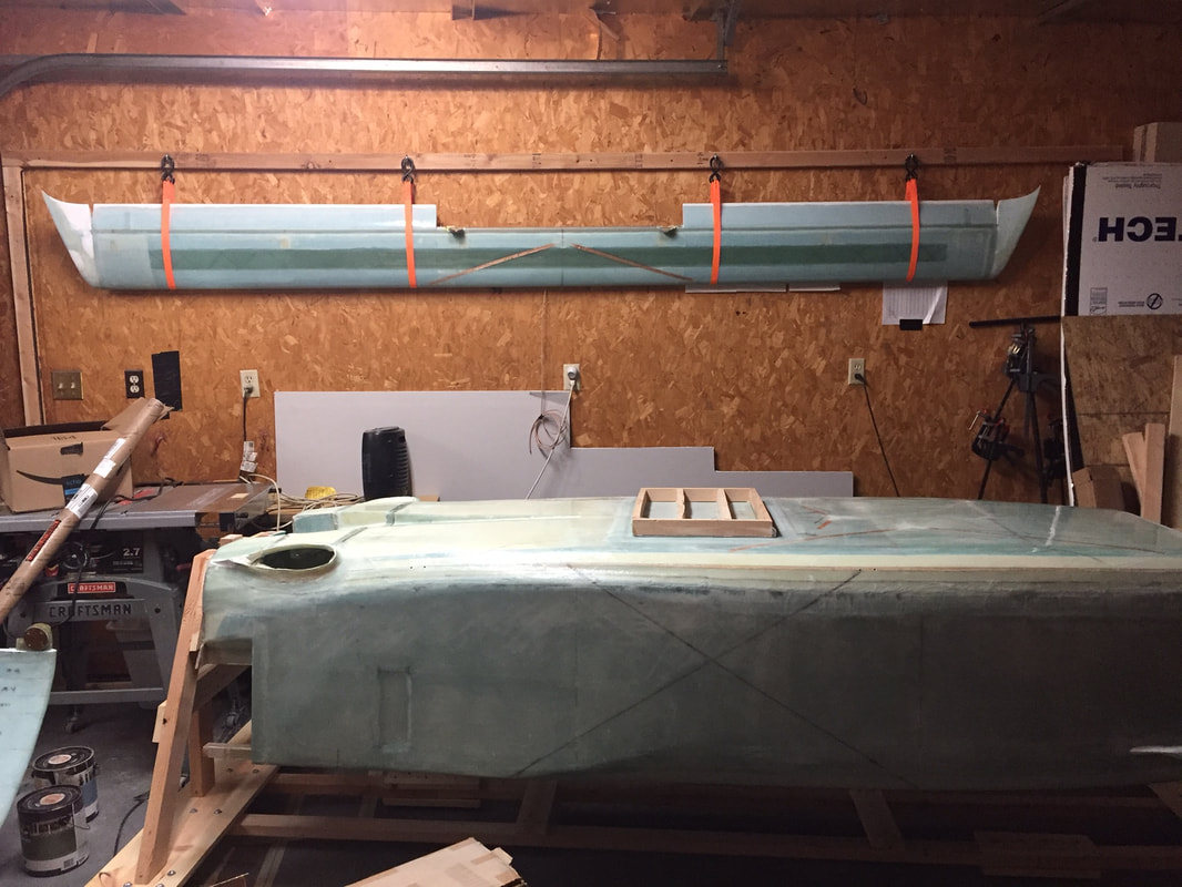
First order of business was to get the fuselage off the rotisserie. I decided to place it on 2 x 4s on top of paint cans rather than saw horses because it wouldn't be too high to work on. Not sure if it was easier this way. Unfortunately, the shop is getting a bit crowded as I didn't have room to maneuver the table around and I just didn't want to bother disconnecting the two parts of the table (read I was being lazy). I used the smart level to get the fuselage longerons level both side to side and front to back. I then laid the canard on top of the fuselage in the cutout area and started making the initial incidence check using the G template.
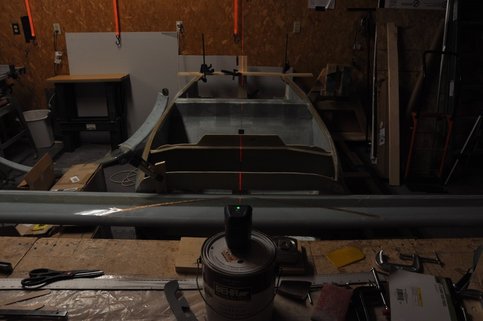
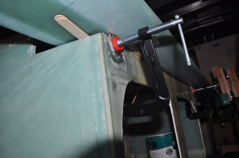
The self-leveling laser line really helped out with checking for everything to be in alignment. It's a bit hard to see, but you can hopefully make out the line. I used a 1x4 with a line drawn and a hole to place string through to raise the centerline at the back firewall. The clamps and extra board are to stabilize it so it wouldn't bend. The laser line helped establish where this board would go. The string was the only type I could find that had as little stretch in it as possible. It still had a small amount of stretch, so I did my best to measure with the same amount of tension and measured several times. It was during this time that I realized my F28 was parallel to F22. I had a definite larger gap on the passenger side. I'll have to deal with this later.
Unfortunately, as you put stuff together, you start to see the inaccuracies in your build. I was no exception. My lift tabs were definitely not parallel to each other nor were they at the right angle for the fuselage. To correct this and to fix the canard positioning for making it even from the firewall centerpoint, I made a BID pad behind each one. One needed a tapered pad to deal with the tab sticking outward from F22. The other just had a normal BID pad. These were peel plied after placing in the correct spots.

After the BID pads cured, I removed the peel ply and rechecked the incidence. The tab alignment was much better, but not perfect. So to correct the last amount and to ensure the tabs have a flat bearing surface, I wrapped the tabs in mailing tape, then mixed up fox, buttered the area behind each tab, and pressed into place lightly clamping down. I rechecked the incidence, alignment with the centerline and the firewall, and the level of the canard before letting it cure.
I decided to follow other builders and make the alignment pins removable. This seemed like a worthwhile endeavor as it makes canard removal straight forward. You just have to remove the bolts and the canard pulls straight up. In order to do this, you will need the following:
- Aluminum tubing with a 3/16 ID
- 3/16 inch drill bit
- A #10 drill bit long enough to drill out the tubing
- AN3-40 bolt (may need longer or shorter depending on how the install comes out)
- K1000-3 nutplate and rivets
- 1/16 inch aluminum plate
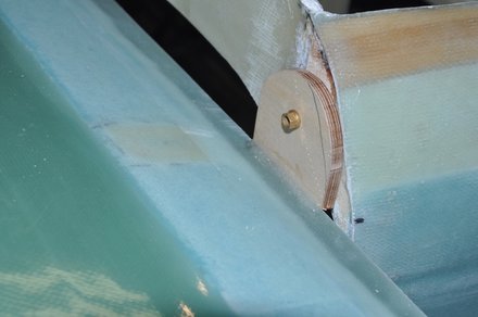
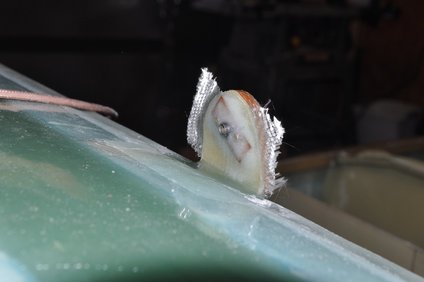
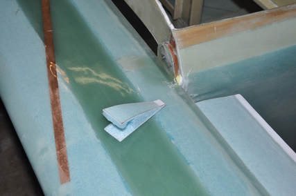
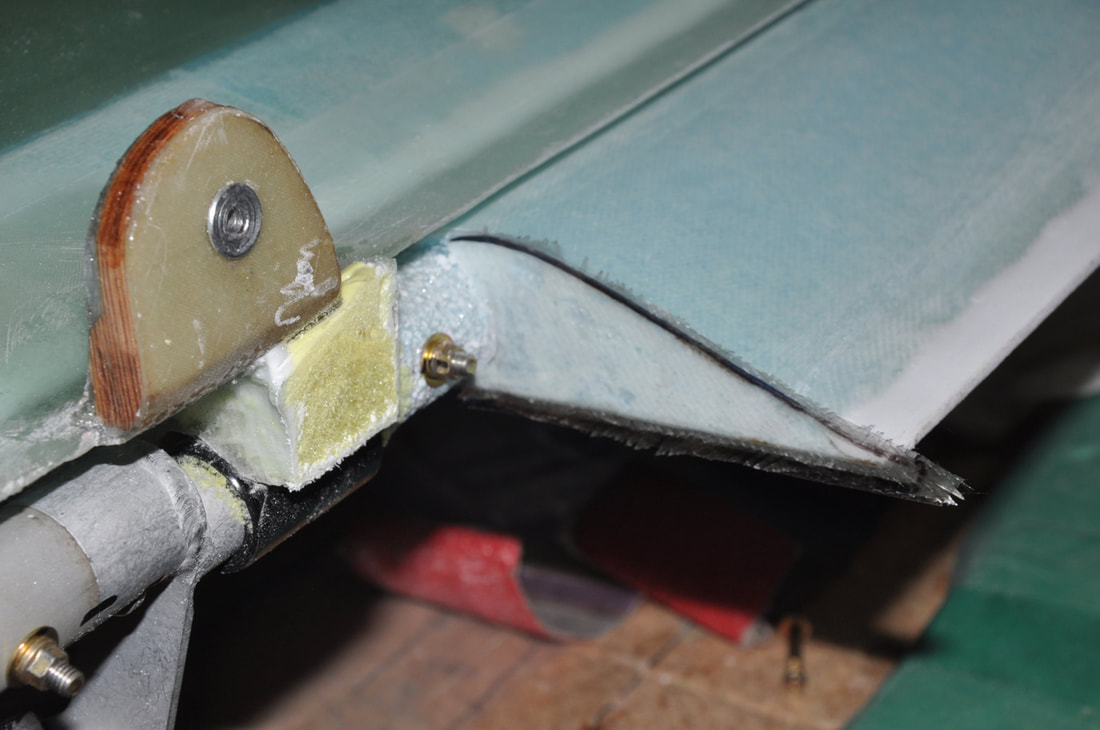
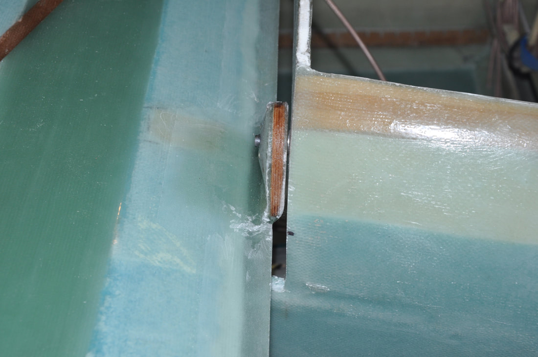
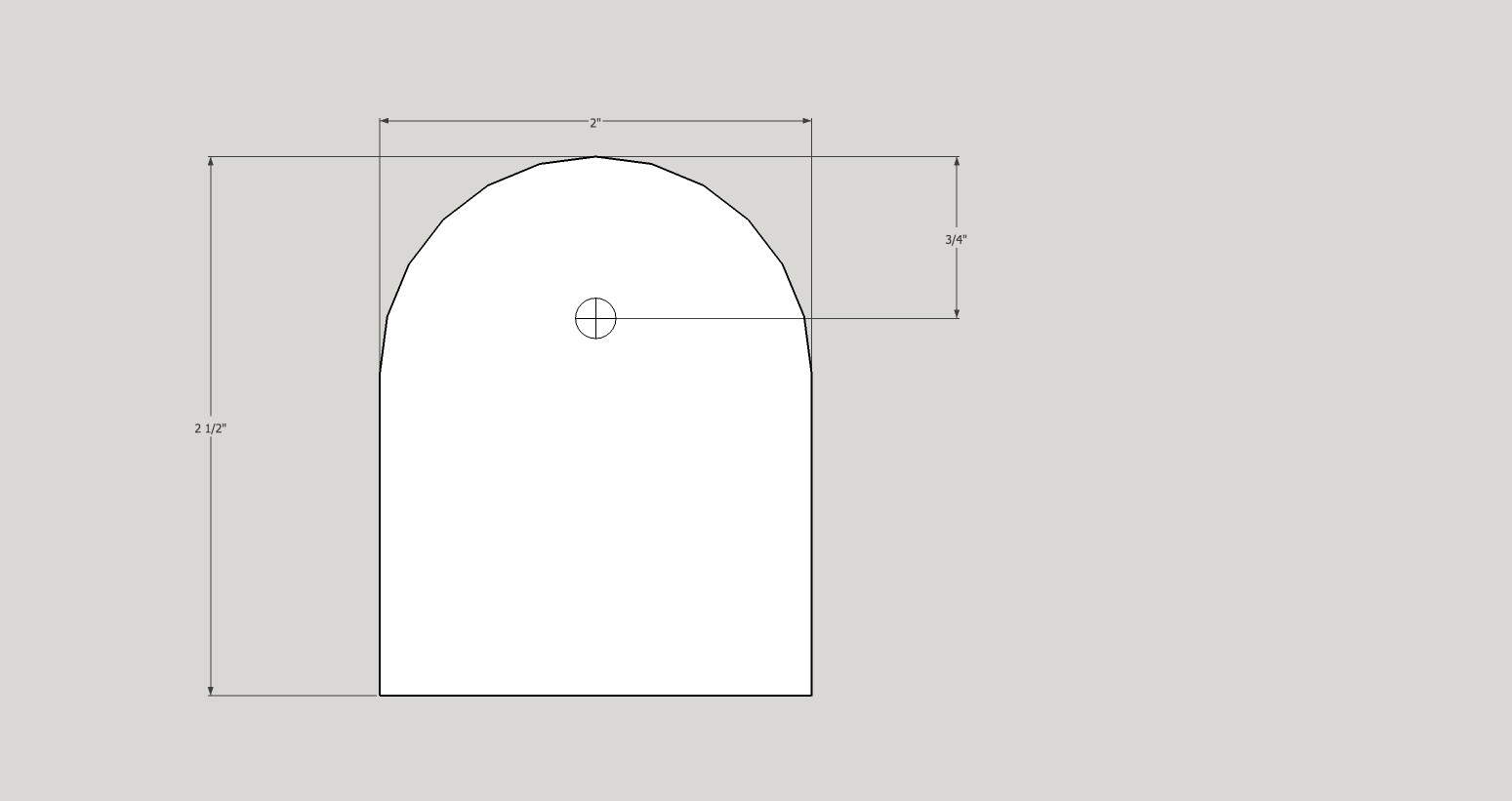
While the lift tabs were well stuck and clamped to F22, I decided to make the alignment tabs. Following what several others have done, I chose to use 1/4 birch plywood. I have included a copy of the template for the tabs below. I'm sure the foam is fine, but I'd rather not worry about it. First I cut out the tabs using a template that I made based on the plans. It was made intentionally long in order to allow for easier adjusting. I then checked the fitment of each tab and adjusted. Due to the gap on the passenger side, I cut a second piece with a tapered edge to make up for the excess space. I placed the main tab towards the back to be close to F28 with the extra piece up front to attach to the trailing edge. Once the pieces were trimmed to fit, they were 5 min epoxy attached in place while keeping a 1/16 inch gap between the tab and F28. I used two AN960 washers as spacers.
| canard_upper_tab.jpg |
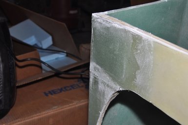
After the epoxy cured, the surface of the canard was sanded and 5 ply BID was overlapped over the forward face of the tab and onto the canard as directed. I had to allow for longer layup for the passenger side due to the spacer I had to add in. After cure, this was trimmed up. I also found that I had to sand away parts of the outside edges of the tab in order to remain inside the fuselage. Don't know if this is a common problem, but other pictures shows it real close for others to the outside edge, so I did what was needed. They should still be plenty strong especially since they don't carry the main loads in flight anyway.
After that, the #10 hole was re-opened. I rounded the back edge to allow for an easy glass transition on the backside. I then made the 4 ply BID layup to the backside again wrapping onto the canard. All surfaces were sanded to ensure a good bond. Once cured, the was also trimmed and the hole re-opened.
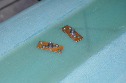
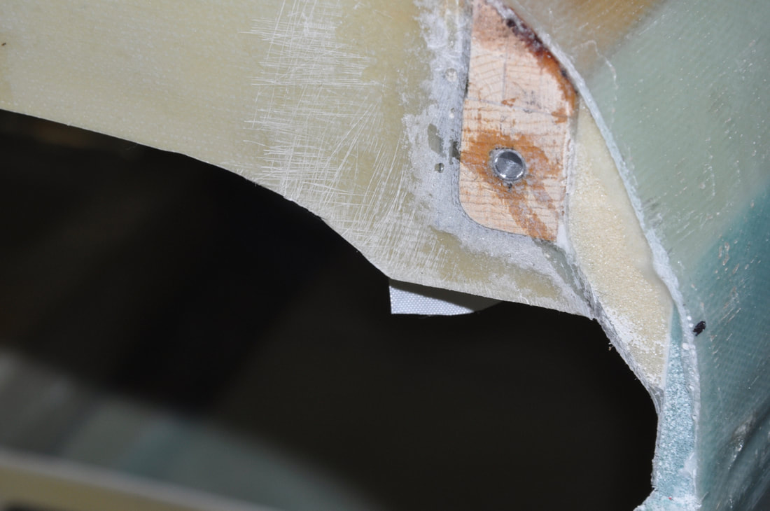
Next, I put the canard back on the fuselage (hey, this thing is starting to get heavy) and saw a large gap still. Not understanding what happened since I used the correct spacer size, I rechecked the drawings. Turns out that the space was for the CN2 bushing that I had not installed yet. I needed to make my nut plates next because I wanted to make sure they lined up with the holes correctly, so I held off on installing the CN2 bushings. I used 1/16 inch aluminum sheet (already had it from other parts) and cut out two small pieces that would fit within the tabs. I drilled, deburred, and countersunk holes for the rivets and the bolt hole. I put the nutplates at an angle so I could drill a couple of holes for flox to fill and allow a good grip on the pieces. These were then alodined. I then squeezed the rivets into place and had two nutplates ready to install.
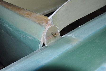
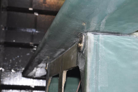
To install the nutplates, I sanded the forward face of each alignment tab, made some thick flox, then carefully used a bolt to pull the nutplate onto the surface making sure the flox did not get into or on the bolt. After that, I used flox to fill in around the plate so that 1 ply BID would transition over the nutplate and onto the tab to help secure everything. To lay the BID over the nutplate, I separated the BID strands in the middle to make a hole so it would fit over the nutplate stud. After cure, the BID was trimmed. As a final thing, I painted the side of the exposed wood with epoxy to help encapsulate it and seal out moisture.
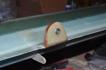
With the plates now attached, I could carefully drill out the hole for the CN2 bushing. I stopped the drill just short of my metal plate. The bushings were then tapped into place with some wet flox under the head to help hold it. The fit was pretty tight, so I don't know if the flox will do much but it's better than not having anything at all (very little was even left after the bushing was fitted, so weight is not really an issue either). The canard was rechecked for fit again at this point. Other than needing some different length AN-3 bolts, everything went together.
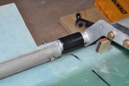
With the tabs done, the next step involved drilling out the #10 holes on the tabs to 1/4" holes. This allows an AN-4 bolt to be installed. With one tab bolted and both upper tabs secured with the removable bolts, the other lift tab is unbolted and drilled out. An AN4 bolt is attached and secured so that the other side can be done without moving the canard.
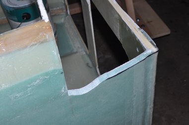
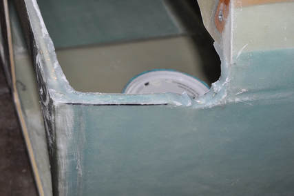
With the attachments done, the next step was to make the clearances for the elevator torque tubes. The elevators were reattached and the clearance was checked. I had to sand away parts of the sides to allow the torque tubes to fit (expected). I went ahead and sanded more than the 0.1" clearance because I'll be able to create a perfect fit later.
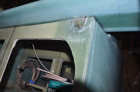
With the fuselage trimmed out, I went ahead and glassed over the exposed edge and onto F28 with 1-ply BID and peel plied. After cure, I drilled out the holes for the canard pins. Flox will be used to help seal up the remaining gaps later.

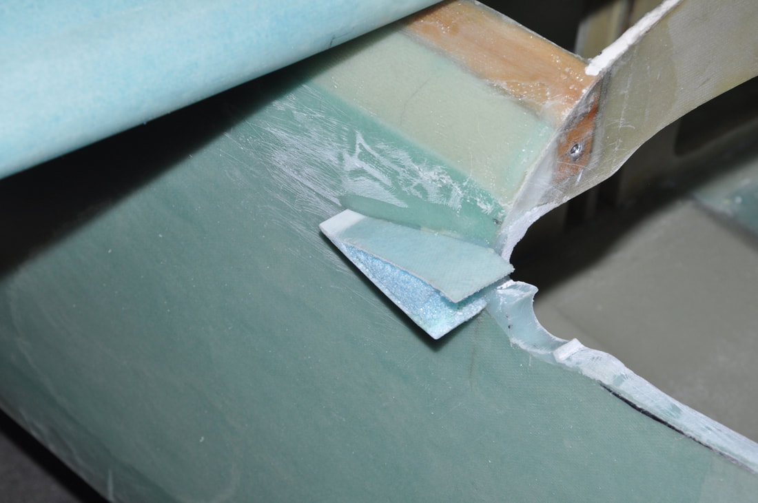
At the same time as making the clearance, you have to trim the elevator to clear the sides. This is where I'm also making a departure from the plans. I decided to follow the Berkut method of cutting the elevator back from the side and adding a static fairing. I didn't want to remove too much elevator, so I only did 1.25 inches. It doesn't completely clear the side of the fuselage with respect to air flow, but it is better. I'll build the fairing later once I get the canard gaps taken care of first. Using the fein tool, I carefully cut away the excess making sure not to damage the torque tube. I didn't bother trying to clean up the micro that was still stuck on for now. This part will be covered by the fairing on the fuselage anyway.
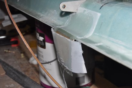
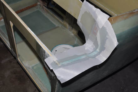
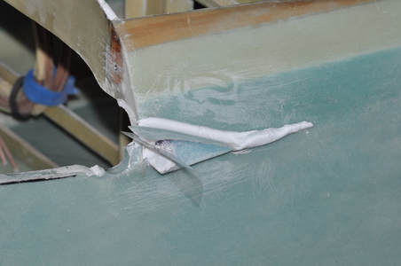
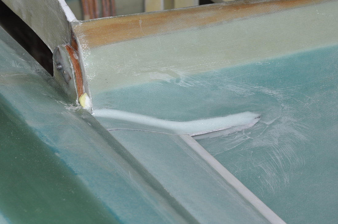
The plans say to fill in the gap where the torque tube resides so that as much of the cold draft air can be minimized. The trick is to leave 0.1" gap all around the torque tube. At first I tried to cut a piece of foam to fill in the area. This quickly became a lesson in futility. I then thought about my Great Stuff spray foam. What perfect item to custom fit an area. In order to prep the area, I wrapped the torque tube with enough electrical to make the diameter at least 0.95" (0.75" + 0.1" + 0.1" since you have to have a gap on both sides of the tube), 1" allows some margin for a glass layer. A layer of mailing tape was placed on the fuselage area to keep the foam from sticking to the fuselage. Once the canard was re-attached, foam was sprayed into the cavity and allowed to cure.
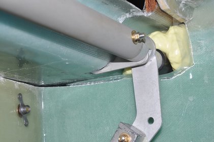
After cure, the foam had made a nice fill with some excess coming out the sides. I had to trim the excess and the foam directly aft of the torque tube. This allows it room to be removed. Otherwise, you wouldn't be able to remove the torque tubes. The rest of the area will be filled in with flox after the foam has been glassed over.
After trimming the foam and ensuring there was enough room, I microed the foam and glassed with 1- ply BID. I didn't have the greatest amount of time to do this one, so it's hardly my best layup, but hopefully it's functional enough. After all, it'll be buried and not seen a whole lot anyway. I left this to cure before I trimmed it. Unfortunately I had to trim some of my layup because I didn't have enough clearance.
After verifying the fitment, I taped over the canard to act as a release layer anywhere it made contact with the fuselage. Wet flox was mixed up and placed all along the top of F22 and in the cutout area for the canard. The canard was put in placed and bolted up. Excess flox was removed and gaps were filled in then the whole thing left to cure. Once cured, it took awhile to get the canard off (maybe needed some wax on the tape too). After I removed the canard, I had a fairly good fit with minimal gap.
I removed the tape from the torque tube and sanded away any excess flox that was in areas. I had the nice 0.1 inch gap between the torque tube and the flox (or at least very close to 0.1 inch). There was some excess flox that rubbed on the torque tube when I moved the elevator, so that was removed. Once the torque tube cleared the flox, I verified that the canard would bolt up properly. For whatever reason, my lift tabs no longer fit flush with the surface. So I redid the flox pad to make a flat surface contact once more.
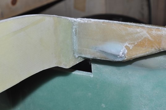
To make the intersection fairing for the elevators, I retrieved the elevator ends I had cut off in Chapter 11. This is a great way to reuse something that will perfectly match the elevator contour. I used a board and hot glue to hold the elevators at 0 degrees to align the fairing. I then started trimming to fit the fuselage side and leave a 0.1 inch gap between the elevator and the fairing. The fuselage was sanded and the piece was floxed into place. I was able to use some stir sticks and cards to help hold it in place for cure.
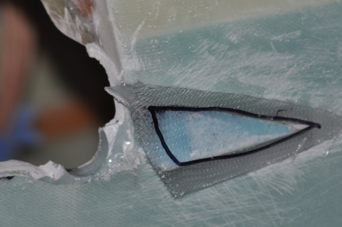
After cure, I checked the fitment with the canard. Due to the bolt that is in that area on the torque tube, I had to trim the fairings back to allow clearance when the elevator moves. The exposed foam side was taken care of by removing a small amount of foam to make a flox corner around the edges of the glass, filled with flox, then the rest of the foam was covered by micro and the outside glassed with 1 ply BID. For the foam that was on the inside area where it use to be attached to the torque tube, I used a round handle wrapped with sand paper and sanded it round again then I filled it with micro then used a small piece of plastic to help smooth and spread it out to retain the needed clearance. Probably not necessary, but it'll look better.
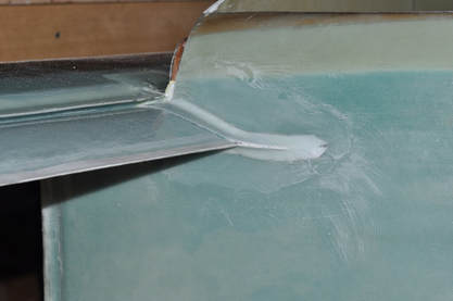
Once all the glass and micro was cured, I trimmed the layup then contemplated the trailing edge transition. The purpose of this piece is to be a drag reduction. Since the fuselage is suppose to be around 2 degrees nose up in cruise, I decided to transition the edge to a 2 degree angle. It wasn't a great change from having the canard elevator set at 0 degrees, but it was a small amount (at least for my plane it was). I sanded the area to bond the micro, mixed up dry micro, then pressed it into place and building up the area to allow shaping later. I wonder if making a mold and building the piece off the plane would have been easier, but oh well. Once cure, I sanded it into profile and shaped it the best I could imagine. I made sure to fillet the corners so that I could lay up 1 ply BID to help attach and hold both the micro and the fairing piece to the fuselage. I peel plied all the surfaces then trimmed after cure. It's hard to say how it will do drag wise but I'm hoping it looks good. With that I close this chapter.
One could continue onto Chapter 13 and build the nose. However, it has been recommended to do all the internal items while you can still use the rotisserie. So I skip to Chapter 16 to start the controls, will continue onto Chapter 17 to do the trim system, then finish up with Chapter 24 to do the covers and fairings that are inside the fuselage.

