Chapter 9a: Main Landing Gear
Now that the tub is done for the time being, attention is turned to the first piece that gets added on to it, the landing gear. This chapter will focus on the main gear for the plane. This is also the first chapter where I'll be listing specialty tools that will be needed or helpful.
Special Parts Needed / Where Used
- #10 drill bits - Used for drilling holes for MG-2 plates
- 1/4" drill, 12 inches long - Used to adjust mounting holes if needed
- 1/4" pilot bit (solid rod) (need two) - Used for checking hole alignment
- 100 degree angle counter sink, 3/8 inch wide body (suggest a Microstop bit setup) - Used for countersinking screws on MG-2
- Deburring tool - Used to remove the rough edges from cutting
- 5/8" hole saw with 1/4" pilot hole (Ace Hardware brand works well) - Use instead of spot facing tool to bore holes in mounting points
- 5/8" reamer - makes the hole accurately sized
- 3/4" hole saw with 1/4" pilot hole - Used instead of spot facing tool to bore holes in mounting tabs
- Right angle or tight space drill - Used for drilling holes in the landing gear box.
Tips and Hints
- Use paper templates for the LG bulkhead re-enforcements to be able to cut the glass out to the correct dimensions.
- If you plan to install the Eureka CNC gear leg fairings, skip building the conduit and trailing edge and just wrap the UNI as indicated in the plans other than you will be coming together on the trailing edge this time (similar to the first wrap, but ending on the other side). The fairings have a conduit built in.
- Mark both the trim line on the gear leg and the 8º trim angle starting from the marked trim line. Then just make the cut along the angle. This will save you from trimming twice per leg. Also note that two different angles are mentioned in the plans. Use the 8º angle.
- After trimming the gear to the required length, you may find that the spread is less or more than the 67.5 inches called out in the plans. This apparently can be caused by the cure process outside the mold. Unless it's grossly off, this is okay.
- When placing the gear legs against the board to set the markings for installing the jig, if one side isn't touching the wall when the forward edges are equal distance from the board, this is also okay and also from the cure process. Nat had 3/16" gap on one side.
- When cutting the holes in the tabs and the bulkheads, use a hole saw with a long pilot bit to go through both guide holes. The plans method of using the spot facing tool is not the best method. Also, ignore the directions that say to make a 5/16" hole and just make the 5/8" first. Also, for the 5/8" hole, grind the hole saw down to slightly less than 5/8" then do final reaming to 5/8" for a precision fit.
- If you order the premade MKMGA part from CG Products (I did) check the thickness of the tube. Due to the diamond grip pattern on the tube, the thickness is a bit more than 0.75" (It's more like 0.76") and adjust your hole size accordingly.
- When you get ready to bolt on the MG-1 and MG-2 plates, make sure to use an AN960-10L washer underneath each nut. The plans didn't make it clear, but the M-drawing shows them. Also, it's good practice to have a washer under every nut.
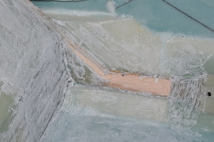
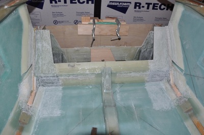
This chapter starts off by adding re-enforcements to the landing gear bulkheads. I previously sanded the bulkheads in anticipation for this, even over the peel plied areas (I wanted to ensure a proper bond). The first one is done on the front bulkheads and consists of three ply BID that cover a large portion of the area and two ply BID that cover over the hard point. First thing was to taper down the doubler in the corner so it wouldn't stick out so much and the glass would be able to make a nice transition. I tried to do the belt sander, but at one point I accidentally sanded part of the inside wall away! So I switched to my sanding tip on the fein and used it to sand down the wood as well as round over all the sharp corners. I then drew out the area that the glass was to go into. This helped to know where it would get placed. I used the sanding attachment to then sand dull all the area within the lines.
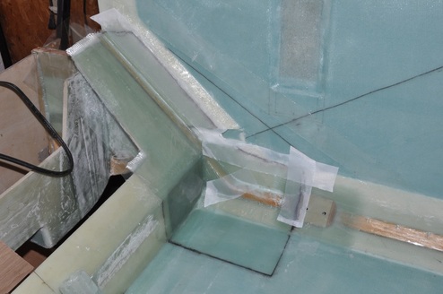
Next, I used paper to make a template of the area. I had to cut the paper at one spot at the corner in order to get it to conform. Once the template was made, I laid it out flat, then cut the BID to size. Now this method will require the cloth to be cut in the corner, but since the plans mention that this can be done, I wasn't worried about doing it. All the glass was cut prior to glassing. I also cut out glass for the small repair I needed to make since I sanded away the glass near the doubler on one side. To lay up the glass, I microed the sharp corners with dry micro, then I brushed epoxy on the entire area within the lines. Next I laid down the first of three plies starting on the floor area and worked upward. I left the excess loop of fabric at the corner, cut a dart, then cut enough away to leave only the required overlap. For each layer, I made the cut in a different area to avoid making too much of a bump. This worked well. I then laid up the two ply BID over the hard point, which was considerably easier to do. The large flat areas got plastic ply to smooth out, remove air, and remove excess epoxy. The contoured areas got peel ply to make sure the edges of the cloth were smoothed out. I didn't put peel ply over the entire internal area because I didn't want it lifting up since it doesn't like to conform as much. This has caused problems in the past. I was able to glass each side in about 1 hour each, so this seemed to work well. This was all left to cure. The plans mentions a BID tape across the landing gear - bottom joint, but I already did this when the bottom was installed (and honestly can't see why it would have been better to wait).
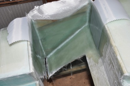
After cure, the excess was trimmed away using the fein tool. I was rewarded with no repairs needed. All the layups looked good. A few edges didn't smooth down so a bit of sanding was in order, but nothing bad. So now attention was turned to the internal LG layup. This one covers the area between the forward and aft landing gear bulkheads. This too is a 3 ply BID over the entire area and 2 ply BID over the hard point. Just as before, a pattern was made from tracing paper and the fabric was cut out minding the orientation of the fibers. The area was sanded down just as before with the previous layup. The fabric follows the line of the bulkhead ears (like the ones done when the bulkheads were made).
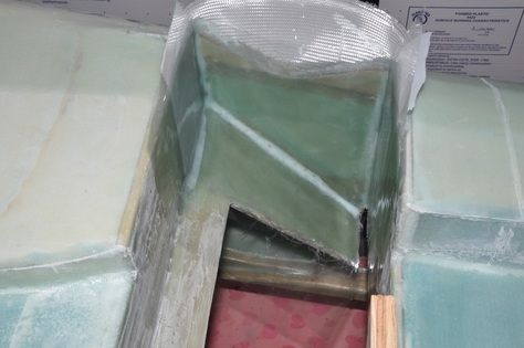
The layup went much like the first, though it took slightly longer, most likely from the limited access of the area. Dry micro was squeezed into the corners using a plastic bag. This worked very well at getting to everything and making a controlled bead size. Next, the entire area getting glassed was wetted down with epoxy. The first layer of glass was lined up with the edge of the upper bulkhead and slowly worked into the the cavity pushing the excess towards the bottom of the fuselage. I figured it would be far easier to cut excess here than at the other end, but both areas would work. Surprisingly, I was able to keep the BID orientation fairly straight despite the odd working environment. Also, I had no need to cut the fabric to get it to fit in the bend like I did with the other side. Everyone else seems to be able to do this as well. I continued to wet out and add the other two layers. The last two are straight cuts that go 5 inches onto the bulkheads and extend up 6 inches. It wraps around along the side to join the two areas. These were very easy and didn't require much effort. I placed peel ply over the hard point since metal plates will be attached here later. The rest was plastic plied to smooth it out, remove excess epoxy, and remove air. I used the rotisserie to do the first one with the fuselage on it's side which made the first layup easier. The other I did with the fuselage upside down since I didn't want the first layup to be upside down and encourage it to pull away. It was slightly harder, but nothing terrible.
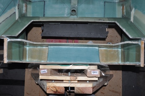
After cure, this layup was also trimmed. These had a couple of small bubbles in the corners, so they were drilled and injected to repair. Now attention could be focused on the last set of layups. This set happens in three stages. The first is a 2 ply BID over the exposed foam inside the box made up by the firewall and the aft landing gear bulkhead. The second is a set of 3 ply BID that covers the vertical faces from the hardpoints to the firewall including the side wall where the electrical duct is. The third is a set of 3 ply BID that covers the hard points and the firewall going across the bottom and overlaps the edges of the first two layups to join everything together. It's getting mighty beefy in this area! I decided to do these layups in one run though the plans instructs doing them in stages. Funny that this is done in stages but the bottom was suppose to be glassed, floxed, and taped in one sitting.
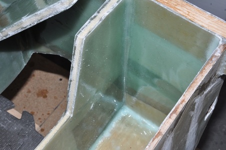
For the first layup, the foam was rounded over on the exposed edges to help the glass lay down correctly. Stiff micro was mixed up, added to a sandwich bag, and piped over the corner joints. Micro was applied to the foam surface for preparations. The BID was wetted out on plastic, then transferred to the surface. After squeegeeing the surface to get the glass down and the excess epoxy out, the surface was plastic plied across the top only and the edges on the bulkheads were peel plied to smooth out. The second was treated much the same, but a template was made to get the size of glass to cut. This was also wetted out on plastic, the corners microed, then the surface is coated with epoxy to help the layers stick. I forgot to add the epoxy on one side and had trouble with air bubbles later, so need to remember to do that. The third was fairly simple without any strange bends, so it was wetted out on plastic and applied to it's place. All the joints were microed by this point. After getting air and excess epoxy out, as much of the surface was plastic plied to smooth out, remove air, and remove excess epoxy. Only post cure issues were on the one area where I hadn't painted the surface prior to adding the BID. These were repaired and then the re-enforcements were considered done.
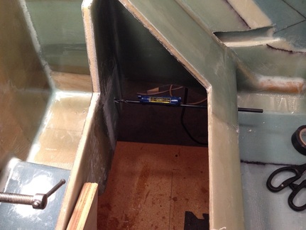
The next thing that was needed was to open up the 1/4 inch holes again. However, since I can't get the drip in between the bulkheads, I have to use the long bit and go through the front holes. Doing this found that they were not lining up properly. I couldn't tell if it was from bad placement from the start, or I didn't drill out the first hole flat enough and I was skewed. To solve this issue I had to do a bunch of measuring and reading to make sure I knew how these holes are suppose to line up with the fuselage. First things first, a visit to the M Drawings shows that the 1/4 inch holes are parallel with the centerline and parallel with the upper longerons. This turns out to be exactly where the rear holes were placed. It turns out the written dimensions were correct rather than the drawn position on the M drawing. So to correct the opening on the front holes, I used a small curved file to open the hole to adjust so that the drill bit would line up with the holes in the rear bulkhead. I used the line level to make sure that the drill bit was level with the upper longerons. I was rewarded with open holes that were where they are suppose to be.
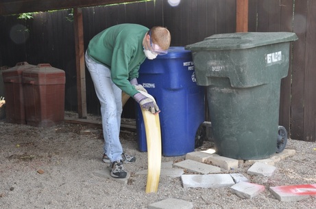
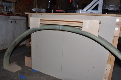
With the reinforcements done, attention can be focused on the landing gear itself. I ordered my hoop from Featherlite. They sent it to me in less than a month after I ordered it. Despite the company name, this piece is anything but feather light, though you really wouldn't want it to be. The piece is a solid S-glass fiberglass hoop that is made within a mold. It came mostly smooth with a few places where the mold seam had been sanded down. The first order of business is to sand down the entire piece to roughen the surface for glass layups. Wearing long sleeves for protection along with my goggles, gloves, and a dust mask I set myself to the task of sanding away at the monstrosity. I used 36 grit sand paper for the job and it took about 1 hour to sand the piece down. Doing this outside saves all the dust in the shop too. Once I sanded the entire piece, I wiped it down and vacuumed of the dust to check for missed spots, then went back to finish up. All the shiny areas should be gone and the entire piece will have a dull exterior. The other thing I did was to find the two areas that were just slightly taller than 5.75". I used my square with a pencil clamped to it, placed the gear legs on a flat surface, then moved it along both sides till I marked the areas that needed to be flattened. I only needed to remove about 1/8" which is all the plans allows. I used the belt sander to flatten them, then hand sanded the edges to bring them back into a rounded profile. This went very quick. I was also glad I did not use the belt sander to do the initial roughening on the leg; it ate up the glass quick.
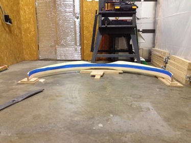
Next order of business is to measure the inside length of the gear legs. The final length should be 95 inches. Most seem to be 96 inches from the mold so I expected the same. In order to set up the correct length measurement, I marked the mid points of each leg end and the center point of the leg. I then used a laser line and matched up the different areas. Once I had my line, I just used blue painters tape (didn't have filament tape handy) and placed it along the line. I don't advocate this but it was what I had available. Once on, I cut the tape at the ends, then peeled off and placed straight on the floor. Measuring it out got a length of 96 inches, so I'm right on with others. That means cutting off 0.5 inches from each side.
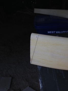
Once the cut lines were marked, I tried several different cutting methods. Ultimately, the fein with a half-moon bi-metal cutting disk worked out the best. It'll be slow going since it's tough S-glass, but it makes a nice straight cut. I decided to follow the plans and make the straight cut and then make the 8º cut afterwards. I thought about doing both at the same time, but feared that I might miss something that I couldn't see right away. We'll see. At any rate, I made a gauge block cut to an 8º slant to mark the cut on the leg. I cut it using the fein again since it worked well before. Hopefully the cuts are symmetrical as possible.
Update: I don't see any reason why you couldn't do the single cut. Find the spot where you need to trim the legs to, then make your 8º mark and just cut once. Just make sure you get the angle direction correct.
Update: I don't see any reason why you couldn't do the single cut. Find the spot where you need to trim the legs to, then make your 8º mark and just cut once. Just make sure you get the angle direction correct.
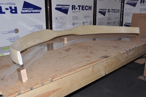
Next up was to prepare the strut for the first 4 ply of UNI glass. Bernard Sui gives a good explanation of how to cut the glass to get the right fiber orientation. Basically, starting at the front point measure down the length of the fabric 65.82 inches. Then go straight up from that point to the other side of the fabric width. A straight line from the start point to this point cuts the very first edge and should be 30 degrees in length. The other end is 24 inches down the fabric ends from both points. This will make a second cut line that is 30 degrees and parallel to the first. You will need four of these for the first lay up then another four for the second layup. The strut gets attached to nail heads to suspend it for work. I made spacers with 2x4 blocks and added 2 inch screws to the tops of these. There were complaints that the plans method didn't leave enough room. This setup worked well, though I should have turned the strut 180 degrees to make the other end easier to work with. Oh well. Make sure that you attach the strut with the leading edge down (the thicker end of the strut). I tried to minimize the amount of glue used on each screw to make the strut easier to remove later. Make sure to put some release material between the wood and the table. I placed packing tape around the blocks to avoid them fusing to the table from epoxy drips.
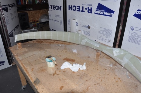
With the strut glued in place, you're ready to do the layup. The thing to be careful about is that the fabric will warp very easily in this configuration. It's important that the fibers be as straight as possible. Also, you want the fabric to only but against each other at the leading edge rather than overlap. The same is done in the middle of strut where the two plies will come together. The other thing of note is that the fibers are suppose to be at 35 degrees to the strut. So I drew guide lines onto the strut to help with proper orientation. To make the layup process easier, I warped the fibers into the widest range possible because the fabric tends to warp towards a narrower profile. After coating half the strut with epoxy, I started the fabric at the center then draped over the rest of the strut with the middle of the strip resting on the middle of the strut. From there I worked the glass down from center of strut towards the end while wetting out the glass and laying up the fibers with my guide lines as best as possible. The hardest area was where the strut increases in height near the center. When I got to the leading edge, I trimmed the glass to get it to butt up with the other side as best as possible. This process was repeated for the other half of the strut making sure to butt up with the first half. The second ply is placed on criss-crossing the first ply, but laid up in a similar fashion. Each ply is criss-crossed over the previous ply till all four layers are on. After that, then whole part is peel plied. I started to peel ply one half of the strut after the last ply was put on to avoid the epoxy hardening before I could add peel ply. I did it by cutting strips and wrapping around the strut. This was time consuming but produced a wonderful result with little post work finish needed. The other side I ran out of time and was just getting peel ply up as fast as possible. It didn't turn out as well and required some work. This was left to cure.
After cure, the peel ply was removed. As expected, the side that was wrapped carefully had a very nice contour all around. The other side had sharp glass edges, small bubbles, and a couple of places that required cutting out a delamination and repairing. These were mostly at the intersection of where the two edges come together, so the repair shouldn't compromise the strength. I also had a lot of peel ply remnants left after peeling it off. I switched to the pinked edge type after hearing how much better it was about strings. Well, the stringer issue was solved, but the pinked edges like to tear off and remain behind. The only effective way I've found to remove them is to sand them off. Time consuming. I'm going to switch back to the regular stuff after this. After the repairs were made and the peel ply was removed, I sanded the entire strut to ensure the best bonding to the first layup for the next layup. I then attached it the supports, but moved the supports so I have better access to the strut this time. Hopefully the next layup will go better.
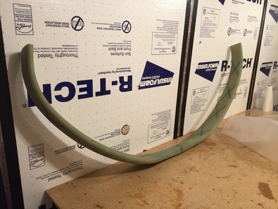
After removing the peel ply remnants and repairing the troubled areas, the entire piece was sanded. Although I used peel ply, it's recommended to still sand the surface. If you look close at the surface, you can see a slightly glossy look within the textured surface, so there may be something to this. So to improve my odds of getting full adhesion, I went ahead and sanded everything. This is one place that definitely needs good adhesion. Once sanded and vacuumed, the second set of 4-ply UNI was added to the strut. Note that I did not do a conduit. The reason being is that I'm installing gear leg fairings so I don't need the built in faired edge. When the fairings are installed, they will have a conduit. So for now, I just wrapped the fabric around just like before, but this time the middle of the cloth fell onto the leading edge. I wrapped peel ply (non-pinked) around the leg vertically in strips which was the way I did it on the side that looked the best, only this time I did the entire thing. This was allowed to cure. After cure and removing the peel ply, I have a very wonderful looking gear leg with perfect contours (not that it'll matter once it's wrapped in the fairing). Excess glass was trimmed from the edges and the nail areas were cleaned up to remove jagged edges.
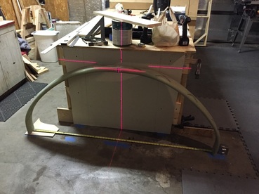
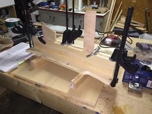
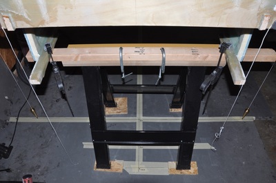
After finishing the torsion wraps, I started on setting up the jig. I cut the necessary wood pieces from a 1x6 on the table saw. Next I used a piece of drywall (had that instead of plywood available) and mounted it to the end of the table. This was leveled vertically as best as possible. Next, the gear legs were placed against the board and the forward edge of the gear leg were positioned at 9.25" from the board face. Two things occurred at this point: 1) My gear legs measured from outside to outside span at 67.825" when they were suppose to be 67.5" which meant I was 3/8" too wide and 2) my pilot side gear leg was not touching the wall with about a 1/8-3/16 inch gap. Archive searching found that Nat said the gap happened to him as well. Turns out that the cure process outside the mold can change the shape a bit. What is important is that the front side of the gear leg ends are at the same point and that the drill points are marked above the gear leg at the correct spots. If one side is slightly higher, then use the higher location. You want these marks to be level if the feet are level. The jigging process is going to take some time and multiple measurements. I had to add about 1/8" to the height of one of my drill points to match them. In order to draw the centerline, I placed a plumb bob down at the calculated centerline on the floor, then used a laser line to line up with the string on the plumb bob so that I was sure I was vertical, then transferred the line to the board and the strut. The image shows the setup with the self leveling cross hair being used to center the strut vertically.
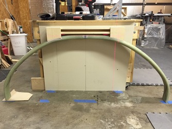
With most of the box done, it was time to add the front tabs. Again, pieces were cut and contoured using the carpenter helper then trimmed till they were level with the top of the box. Once the pieces were fitting, they were attached to the jig box, then the fit was rechecked. Once confirmed good, the jig was attached to the gear leg with bondo. I read that it can be hard to remove the jig if a lot of bondo is used, so I tried to only use enough to cover the attachment area but ensure it won't pop loose easily. You will note that part of the front wood tabs will stick out from the leg. This is normal. You can either use bondo to smooth the transition or some people use modeling clay. Once the jig box is on, the reference lines for the drill holes is transferred to the box. To make it easier, I used the cross hair laser to locate the point by lining up with the vertical line and the two horizontal marks. The two points should be 26 inches apart. Remember to use the higher of your markings so that you have enough clearance for the tubes later on.
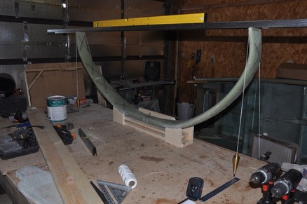
Once the points have been placed on the jig, it's time to mount it to the table. You draw out several alignment markings onto your table, make sure the table is level in all directions, then mount the jig to the table, which I did by driving screws through it into the table. It would be a good idea to cover the table with plastic to avoid the jig sticking when epoxy is used. I didn't do this, but taped over the areas where epoxy will be. Hopefully I'll be okay. Now starts the lesson in futile geometry. First you check that you have the jig lined up with the back line and centered on the centerline. Then you need to check that the front edge of each leg is 9.25 inches forward of the back line. To check this, I used two plumb bobs hanging from the front edge of each leg to check (see picture). When I first checked, I was off by 1/2 inch on one side and 1/4 inch off on another. I'm guessing the table moved when I was gluing the jig to the legs. So I carefully removed the bondo, then adjusted the legs in the jig. Amazingly, the legs balanced well in the jig. A couple of small spacers to push the legs back till I was centered and on the line, then I used bondo to set it into the spot. After finishing, my level shows it's level, one leg is right on the line, and the other is ahead by maybe 1/16 inch. This is well within acceptable limits (0.25 inch) and can easily be adjusted later. So I stuck with this.
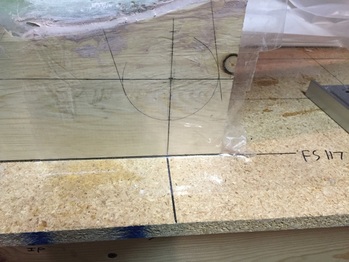
Next job was to redraw the drill point and draw out the tab form. I double checked the location of the holes to make sure they were still 13 inches from the center and they were still all at the same height from the table. To make sure clearance was good, I based the hole location on the one that was the closest to the table top (or the one that was the highest above the strut). I used the inside of a tape roll that was 3 inches wide to draw the tab form. I extended the location marks for the holes outward on the jig and the table so that I could find them after the layups were done. After that, I covered everything with packing tape for the eventual flow of epoxy when the tabs are pressed.
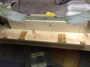
It has been suggested to make the clamping boards for the tabs long enough to stretch across both tabs in order to keep thing straight. It is also good to add 1/2" spacers on the boards to keep it from clamping too hard on the tabs. I calculated what the thickness should be with the 45 layers and it came out to 0.49" so 0.5" spacers are nearly perfect. I glued these on then covered the board with packing tape. This left it ready to be used for clamping the tabs. To prep for the tab layups, the area was sanded dull (even though I used peel ply) and the glass was cut. There will be 25 layers of UNI and 20 layers of BID for this layup. I drew out the cut template for each type on plastic so that after the glass was wetted I could then cut the proper sizes out.
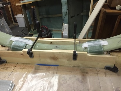
After all the prep, the large layup has arrived. I layed out plastic sheet and placed the first layer of UNI down. Mixed up a batch of epoxy and wetted out. Then I laid the next layer down and continued till all 5 were wetted out. I then placed plastic on top of this, squeegeed out the excess epoxy that I could and removed any trapped air between the layers. I placed my drawn template under the sandwiched glass and used my electric scissors to cut through the glass and plastic to make sandwiched strips. The scissors were able to cut through all those layers. If your measurements were correct, you end up with 10 strips that are 3.8 x 15 inches. I just peeled one side of plastic off, then pressed into place across the strut using my drawn template as a guide. While the plastic was still on the outside, I squeezed out as much air as I could with the squeegee, then peeled the plastic off and used a brush to make sure everything was pressed into place. This was continued for the other four strips, then repeated on the other side. The same thing was done for the BID, but there were only four layers to wet out and the 3.8 x 15 inch strips are cut in half to make 3.8 x 7.5 inch strips. This allows the BID to reach all the way down the tab since at this point things are getting thicker. The trick here is that the glass starts to slide around easily with so many wet layers, so it gets tricky to work the air out. In the end, I was able to get all the strips in place with fibers fairly straight, then peel plied the top to smooth the transition of the glass where the BID was cut. I then used my spacer clamps and clamped down on the tabs. I almost had the thickness perfect as there was only many 1/16 inch of compression when I clamped the piece on each side. I also didn't get the waterfall of epoxy that others reported getting when they do this. It's good to get some compression as you want the faces to be flat for later on. Hopefully, I taped the pieces enough that they won't be stuck on after cure. This whole process took me about 4 hours to do.
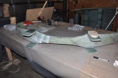
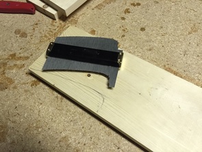
After cure, I drilled out the 1/4 holes using the drill jig and my alignment marks. I made sure that the jig was vertical before drilling. The clamps and boards were removed. The tape job worked well as they were not stuck on. I little bit of epoxy squeezed out, but not much. The forward side of the tabs does bulge around the leading edge of the gear leg, but I've seen others with the same appearance, so I suspect this is normal. It took a bit of chipping away at the bondo to remove it. Once I got the bondo cracked, I was able to pound the jig free from the gear leg (tight fit). Everything looked good. There was some bondo stuck in the crease between the gear leg and the tabs that took some scraping to get it out. Once cleared up, I checked the hole alignment by passing a 12 inch 1/4" bit through one tab to the other. Both sides lined up! I got my tab template out and started drawing my tab outline for trimming the excess. I was relieved that they all had enough material to cut and leave full thickness tabs meaning they layup didn't move from where I originally put it. You can see the tab template with a 1/4" bit used to pin it in place.
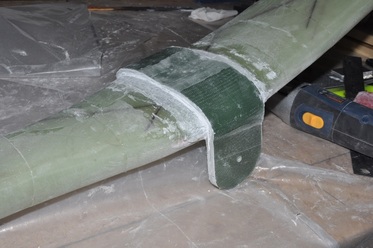
To trim the excess tab material on the strut, I used the fein tool to make cuts a few layers above the strut while cutting along the trim line. I just kept going between the horizontal cut and the vertical cut to ensure I didn't cut anything important, then chiseled out the excess glass. After trimming the excess, I sanded down the remaining, though I left a few layers in order to avoid sanding the torsion layups. It's not the prettiest, but it removes the excess weight and gives you a good idea of what the cross section looks like (nice compressed layers, no voids, etc...).
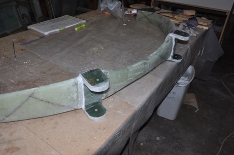
Next job is to do the second layup for the tab. This one will use 20 ply of UNI (instead of 25) and 25 ply if BID (instead of 20). Prior to the layup, the inside surfaces of each tab were sanded dull, then I placed masking tape over the bottom side of each hole in each tab, then covered the surface with masking tape leaving the hole exposed. Using a candle, wax was dripped into each hole till they were full. The masking tape was removed (the bottom piece kept the wax from dripping out, the top kept the tab wax free as wax would be bad for the layup). The area on the strut that was between the tabs was also sanded dull in preparation for the layup. The layup was done the same as the previous one with the UNI remaining in the full strip and the BID cut in half strips. Since this is the inside layup, the strips don't have to be as long (15 inches), but I had already cut the fabric. You could take 1-2 inches off the length and still have plenty (verify first though before taking my word for it). I wasn't as careful clamping this layup and some of the strips moved a bit. It's okay, but it wasn't as perfect as the first layup. After cure, I trimmed the tabs using the first trim as a guide for the second trim. The excess was removed the same as before. The tabs are now 3 inches wide. The wax was then removed and the holes drilled out on both sides. I rechecked and the bit was able to go from one side to the other, so the holes are still aligned.
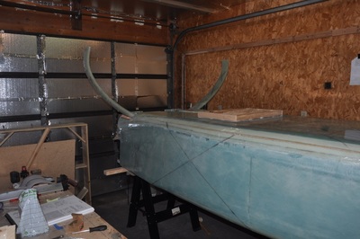
At this point, you are suppose to check the fitment of the strut to the fuselage. So I set the fuselage up on saw horses and placed the (heavy) strut in the mounting area. Using a wood block to hold the gear leg up high enough, a 12 inch bit was used to check the alignment of the tab holes with the bulkhead holes. Though it was tight fitting, all the holes were aligned on the first try on both sides. It's nice to see something go right, though I have some skepticism due to the tight fit. The next step is to check the alignment of the strut to the fuselage. For this, I placed lines on the floor that represented the centerline, the firewall, and FS 108.25 (front edge of gear leg). These lines were made by dropping plumb bobs down the centerlines on the bulkheads, then using a large carpenter's square and laser lines to find the line placements. Once marked, the landing gear was adjusted to center in the mounting area. With the gear centered, the forward edges are on 108.25 and 108.35 (the 1/16" I was off before) and the legs were level on the fuselage. This is good! Next step is to start boring a bunch of holes.
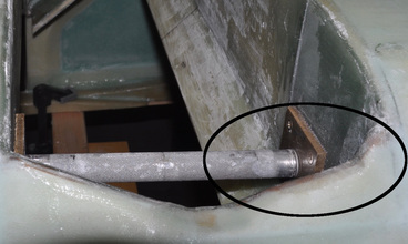
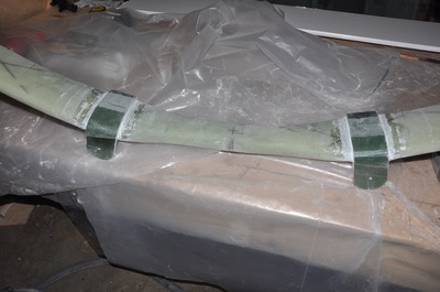
I did find while checking the fitment that I wasn't going to have enough clearance between the gear leg and the fuselage. There were references to this causing cracks later on if the plane had a bit of a hard landing. From what I could find, you want at least 3/8" clearance, I decided to make it 1/2" for better margin. So I went ahead and cut off some of the material from the triangles that were installed previously. I then covered it over with the same plies and type of glass that was used in that area. This created the needed clearance. You can see the modified area in the circle.
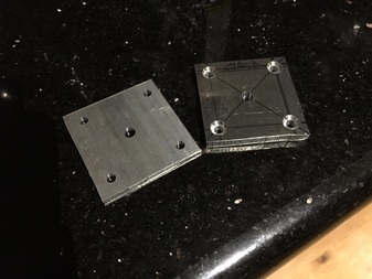
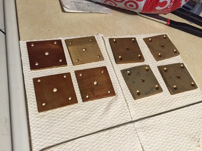
First up is making the MG-1 and MG-2 plates. MG-1 uses 1/8 inch aluminum while MG-2 uses 0.25 inch aluminum. I cut these out on the band saw. I won't win any awards for my metal working skills, the blade didn't want to track straight so some edges are a bit curved. After cutting the plates, the holes were located by drawing reference lines. I used a center punch to make a dimple to help the drill bit center in the right spot. The center hole is 0.25 inch and done on all pieces. MG-2 gets four #10 holes drilled out at the corners. These holes are also countersunk with the 100 degree countersink. After cutting everything, I used a deburring tool to debur each hole and the edges of each piece. Except for my band saw cutting, the parts looked pretty good.
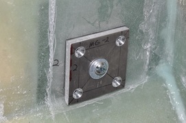
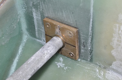
With the pieces cut, I then used a 0.25 inch pilot bit to fit the plates in and mark their locations. MG-1 go on the outside of the mounting box while MG-2 go on the inside of the mounting box. Like others, I found that the MG-2 plates on the forward side of the mounting box had some interference from where the slanted bulkhead was located, so I used an angle grinder to camber the edge enough to clear. Once fitted, I used hot glue to glue the pieces to the bulkhead. Heating the aluminum up with a hair drier allowed me to press the piece into place before the glue set. Hot glue makes it easier to remove the part later on. Once glued in, the pilot bit was removed. From here, you drill out the #10 holes using MG-2 as a template. To keep the pieces from coming loose while drilling, a 0.25 inch diameter bolt, nut, and a couple of washers are used to clamp them together. To aid in the drilling process, I found it easier to drill through the fiberglass and enough into MG-1 to leave a divot, then I could finish drilling on the drill press. Drilling through MG-1 on the fuselage took a lot more effort. and by doing it on the drill press you avoid heat buildup near your fiberglass. After removing all glue and finished drilling the pieces, I deburred the holes on the MG-1 plates, sanded the back surface of both MG-1 and MG-2 rough, then cleaned and alodined the parts. I thought about doing the alodine after the 5/8" hole, but then things could shift and the area that would be exposed will be embedded in flox with a fitting on it, so I wasn't too worried about it.
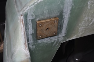
After alodine treatment, I sanded the mating area on the fiberglass for a good bond, vacuumed clean, then applied flox to both the aluminum and the fiberglass. Using the 1/4" pilot bit to make sure things stayed aligned, I used the screws and nuts to pull the plates tight against the bulkheads and to squeeze out the excess flox. Excess flox was scraped away and the parts allowed to cure. I had to buy screws that were slightly longer. For some reason my bulkheads were a bit thicker, I'm guessing. I was actually surprised because my layups are usually on the thinner side. Oh well. I waxed the bolts just in case I ever have to remove them down the road. I made sure to remove any wax from the threads before putting the stop nut on.
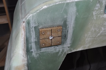
After cure, I found out a couple of my aft 1/4 holes were just slightly too far in. I verified this against the centerline mark on the fuselage. The forward holes were okay, though I had sand down one side of the hole to allow the bit to angle. The holes were either 1/16 - 1/8 inch out for some reason. Before going on to the next part, I wanted to correct the hole alignment. First I verified that the hole alignment was off with the strut (it was), then I filled the hole with flox and allowed to cure, then I clamped a drill guide in the correct location so that the bit would stay on target and drilled the new 1/4" hole. Even with the clamp, the drill didn't want to drill through the aluminum as much so I still had some adjusting to do afterwards. I had to use my 1/4" straight flute router bit to cut away till I reached my needed point. After drilling out the new guide hole, I checked the fitment again and things are now looking good. This extra hole won't matter much because when the 5/8" hole is made it will be gone anyway. Still, good to know in case anyone else has to do it.
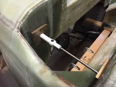
Next I prepped the 5/8" hole saw for cutting the holes through the bulkheads. I wanted to trim the saw down to slightly less than 5/8" since I would use the reamer to finish the hole to the correct size. I attached the hole saw to my drill press and used my angle grinder to take down the outside edge till I got the size I was after. Calipers make the act of checking the hole size far more accurate. Once I achieved the size I wanted, I followed Bernard Siu's method to cut the holes. This involves the following:
- Cut most of the way through the rear bulkhead from the forward face going through MG-2, aft LG bulkhead, and leave MG-1 while running the pilot bit through both the forward and aft bulkhead holes.
- Cut all the way through the forward LG bulkhead by going through MG-1, forward LG bulkhead, and MG-2 while running the pilot bit through both the forward and aft bulkhead holes.
- Finish cutting the aft MG-1 plate using the pre-bored hole as a guide.
- Ream the holes to final thickness.
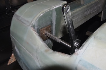
After drilling the holes, the MG-4 bushings are test fitted into the holes so that the mounting studs can be pushed through to make sure they fit straight. Despite using the reamer, I found that I still had to widen the hole a bit. I used the reamer to make sure I had completely cut off all excess material. Once I got the hole cut to size, I fit the MG-4 bushing in on both sides and tried inserting the mounting stud. The stud was just barely hitting the edge of the bushing, so I had to file the hole enough to allow the bushing to move just enough to allow the stud through. I didn't want the fit to be so tight that it would be difficult to remove, but I didn't want a sloppy fit either. Once I had the fit correct on both sides, I made some flox more on the wet side, then added it to the surface of the bushing, carefully inserted the bushing, removed excess flox, checked that the inside was free from flox or epoxy, then inserted the stud to hold the alignment correct. I waxed the stud just in case some stray epoxy got in. This was allowed to cure.
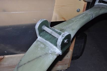
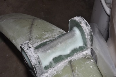
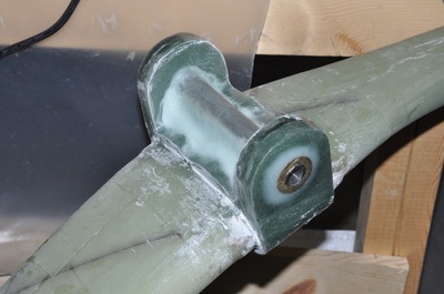
Next we turn our attention towards the tabs on the landing gear. These are mostly the same as the bulkhead holes, except that the hole is 3/4 inch. However, I ordered my MKMGA tubes (preassembled) from the Cozy Girrrls. It's a well made piece and for someone like me who is not a metal worker it makes life easier. One of the things they did was to diamond grip the surface of the tube. This removes the need to drill dimples into the surface for fiberglass attachment. It does, however, cause the diameter to increase slightly in this area. I measured about 0.76 inches over the diamond grip. Because of this, I couldn't ream the hole to 0.75 inches. To do the cut, I tried to trim the hole saw down to exactly 0.75 inches, then sand the remaining needed material. I set up the hole saw so that the pilot bit went through both alignment holes, then took turns drilling each tab a little bit to avoid excessive heat. I also had a cup of water to cool it down. It took awhile, but eventually I had all four opened up. Although my hole saw tested at 0.75 inches, when I checked the holes, they were closer to 0.735 inches. It must have shrunk or it cuts differently in fiberglass than wood. At any rate, I now had a lot more sanding to do. I but a step drill bit that was a max size of 0.75 (checked it with the micrometer). I then took turns running the bit through, sanding, filing, checking, then repeating till I had the opening wide enough to at least tap the tube in with a rubber mallet. A tight fit isn't a bad thing. The tubes only would go in one direction, so I indexed them. To install, I placed flox along the inside of each tab hole and smeared flox over the surface of the tube where it mates with the tab. I used an ear plug to seal the hole of the tube to avoid flox getting in (wax would work also). My tabs were a bit thinner than the expected 1 inch thickness, so I centered the tube with equal amounts sticking out since the strut was centered in the fuselage when I checked the alignment earlier. The excess flox was scraped away from the tab surface and allowed to cure.
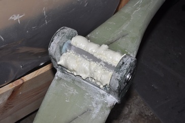
After cure, the plans has you fill in the space below the MKMGA tube with any type of foam. I decided to just fill the gap with Great Stuff which is a urethane foam. My original attempt was to tape the area to make a form for the foam, but this particular foam has a solvent and it didn't cure right. Next time I would just spray the foam and that's it. Just lay down a good continuous bead under the tube going up to it. The foam will expand outward. After the foam had cured, I could cut it with a flat edge bit on my fein tool. I cut at an angle that would leave at least 1/2 inch of the tab layup over the strut visible for the glass to attach to. Once trimmed, I sanded all the exposed inner tab fiberglass surfaces, microed the foam surface, added a dry micro filet where needed, then laid in the 2 ply BID to cover over the tube, onto the tab bottom, and onto the tab sides. I trimmed the excess after cure.
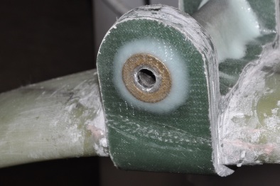
The last thing to do before calling the strut finished is to add a washer to the outside over the tube and flox it in with 2-ply of BID glass on top. Reading the archives, people have mentioned that it's better to have the washer flush with the MKMGA tube surface because some tubes have broken loose from hard landings. If my layups had been exactly 0.5 inches, then one washer would probably have been real close. However, mine were a bit less than 0.5 inches. So I ordered several AN960-1231 and AN960-1231L washers to have both thicknesses so that I could get the right height. Turns out every tab needed two of the standard AN960-1231 washers (at least I'm consistent). This will help support the tube that is outside the strut tabs and hopefully avoid some possible bending issues. So I made sure they were able to fit, sanded the surface, then floxed the washers in place. I also added a dry flox filet to the edges to make a transition for the glass. The glass was laid up in plastic sandwich, the outline of the tab marked and the location of the hole made. I cut the hole by folding the sandwich in half and cutting a semi-circle out of the correct size. Then it was just wet the surface with epoxy, peel one layer away, stick the wet glass onto the surface, peel the other side, and stipple in place. I trimmed this after cure as well. Hopefully this will work out well in the installation.
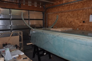
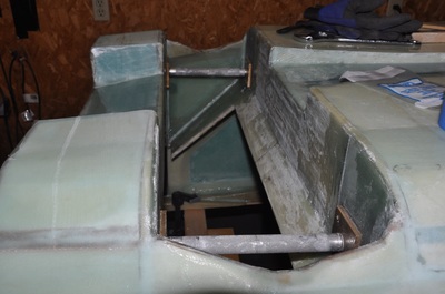
Now's the big moment! Time to see if I can place the studs through all the holes that have taken time to make. One suggestion from the archives is to put anti seize on the stud since it can be a bit difficult to remove later on. You also want to use enough washers so that when the nuts on the studs are tightened the bulkheads are compressed onto the washer stack to make a tight fit. You shouldn't have to deform the bulkheads much to do this, so the washers should be a nearly perfect fit (have different thickness washers is the key here). Unfortunately, this was when I entered the fifth circle of hell (leaving other circles in case things get worse). I was unable to drive either stud all the way through. I could only get one started and the other side would not line up at all. A careful examination of all my holes found that the fuselage holes were parallel and centered compared to the centerline. The tubes on the strut were both angled away from the centerline! Time for a bit of an emotional breakdown. After recovering, I set out to find the error of my ways.
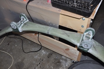
I took some measurements using the studs as a reference point by measuring the distance from the outside edges on both sides of the strut. This gave me the angles that the tubes were at. I then checked the distance from the centerline to get any offset. What I found was that one tube was 2 mm too far out on the front and one tube was 0.5 mm out on the back. So it was close. I've said it before, you learn how good your work is when you have to undo it. I started by cutting away the BID wrap on the inside of the tabs that wrapped around the strut then removed the foam. Next I removed the washers from the outside. This took some heat to remove them using a heat gun. Then the hard part came. The tubes were so well stuck that the only way I was able to remove them was to use a couple of clamps with a flat piece of aluminum and a socket that was slightly smaller than the tube to make a press. While heating the tube with a heat gun, I slowly pressed out the tubes. I had to get the tube fairly hot to soften the flox that was holding them in place. After a couple of hours, both MKMGA tubes were now free. I used my 3/4" stepper drill bit to clean off the flox in the holes.
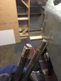
While I was at it, I decided to follow Bernard Siu's example of grinding a couple of flats on one end of each stud. The reason for doing this is that both ends get a lock nut on them. If the one inside the hell hole decides to remain on, then you can't remove the bolt and there is little to hold onto to keep the whole thing from turning. Grinding the two flat spots allows you to use a wrench in case this happens. Well worth doing. I just used my angle grinder and a steady hand to do these.
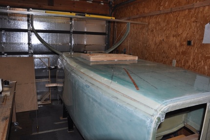
Determined to get it right this time and to provide a path for others that may experience my misfortune, I checked things first by placing the tubes in the fuselage opening and seeing if the stud would run through. A couple of the fittings needed just a small amount of filing to reduce a small amount of binding. It took very little to get the stud to rotate freely and insert with no problem. Okay, problem one done. Next was to fix the strut alignment. First I inserted the MKMGA tubes back into the strut and placed it in the fuselage. I checked to see if the offsets matched by calculations. Then I started with one hole and slowly shaved off material to allow the tube to move over to the right position. This will create some gaps but they will be filled with flox later. There shouldn't be more than 2 mm removed based on calculations. I kept removing the strut, shaving the hole, replacing the strut, then checking the stud for clearance and repeating till the stud went all the way through with no binding and would freely rotate. Keep in mind this strut is rather heavy (I haven't weighed mine yet). Once one side was done, I worked on the other end. The passenger side has about a 1/16 inch gap between MKMGA and the MG-4 bushing which means I must have gotten too much space between my bulkheads. My strut was slightly forward of the 108.25 line when I made the tabs, so I made sure to place the gap towards the front. This was taken up by adding two thin washers with the same ID as the studs.
After getting both tubes adjusted so that both studs were no longer binding, I rechecked the strut alignment. I recentered the fuselage on the centerline on the floor, then I dropped plumb bobs from the front edge of the strut. Final measurements were the following:
After getting both tubes adjusted so that both studs were no longer binding, I rechecked the strut alignment. I recentered the fuselage on the centerline on the floor, then I dropped plumb bobs from the front edge of the strut. Final measurements were the following:
- Strut is offset 1/16 inch from centerline
- Both forward edges were 1/16 inch forward of the 108.25 inch line (no more uneven offset!)
- 0.1 inch incline between the strut ends (nearly level)
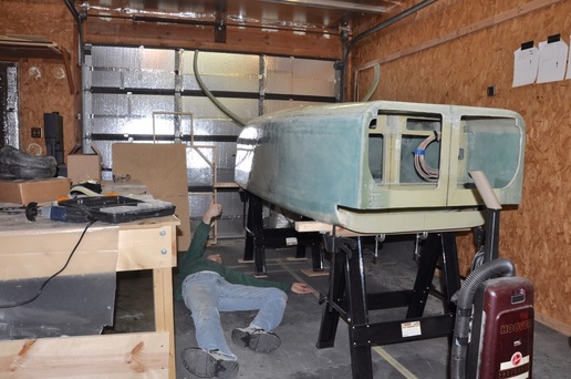
With the tubes checked and the studs still fitting, I then proceeded with the permanent floxing. This involved making sure flox was stuffed well into the cavity between MKMGA and the tab hole. I also replaced the washers on the outside of the strut tabs and then replaced the foam and the BID around the inside. Due to the tight fit, I used one thick washer and one thin washer so the glass would be just even with the tube surface. A final check of the strut installation made sure that it still fit and was still aligned with the marks, then I floxed the MG-4 bushings in place with the studs and strut mounted to hold the alignment, just in case. I made sure there was no flox to stick to the stud, but just in case I waxed the stud to make sure there was no sticking. I now understand why some grind a couple of flats in the threading on the studs. You are trying to tighten two nuts on a stud that if the nut on the forward side comes off before the nut on the aft side then you can't pull the stud out. So I will need to grind a couple of flats in to allow removal. With that, I give my (very tired) thumb of approval and can finally move away from this nightmare.
