Chapter 6: Fuselage Assembly
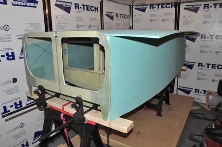
This chapter is where you start to get the first thing that looks like a structure rather than abstract pieces that your family wonders what in the world you're doing. The sides and the bulkheads will all be assembled, then you will create the bottom and attach that to the structure. It's exciting! This is also a very involved chapter, so there's a lot to do.
Tips And Hints
- If you assemble the structure upside down (upper longerons on the table), then it will naturally want to be level rather than having to jig it level as long as the upper longeron edge is flat (sand off any epoxy that dripped over during the side construction).
- Use a self-leveling laser line to help with alignment (wish I had). It will really help with aligning all the bulkheads. Make sure the table is level with the horizontal laser line and the vertical laser line is perpendicular to the table.
- Use a 1/2 inch piece of plywood for the temporary firewall. It will remain straighter than 1/4 inch piece will and create less fitment issues later. The piece can be screwed directly to the end of the table to help hold it in place and keep it at 90 degrees. It also helps to add some stiffening boards to the back.
- A carpenter helper or contour shape tool will allow you to capture the actual contour that bulkheads have to match. Well worth having to make the job easier of fitting pieces.
- Being able to separate the table top will allow the IP to fit through when assembling upside down. This is needed since the IP sticks up above the structure and if assembled upside down it will need a whole to fit through.
- This is where you need to decide if you want to set the seat back 1-2 inches. Most agree that 1 inch really helps if you're a bit taller than Nat. I tried to mock fit things and guess, though without cushions it's hard to know how it'll actually fit, so I went ahead and did 1 inch to be safe.
- To aid with upper alignment, stretch a line of string from the front to the back attaching at the center lines. I had a string screwed to the table at the centerline, ran it up the front of F22, then took it back to the firewall and clamped it to the center line.
- A carbide grit attachment for a fein tool makes short work of any sanding and can get into corners easily.
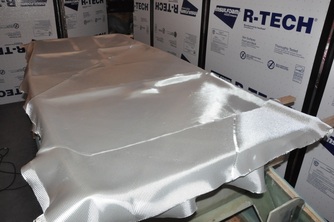
- BID taping is easier to deal with if the glass is wetted out on plastic, then sandwiched between another sheet of plastic and cut to size. The plastic will act as a protective layer to keep things straight and even. You just peel one side, then press into place, then remove the other side of plastic and work the rest of the air out.
- The layups for the landing gear re-enforcement are also easier to do if done similar to BID taping by using plastic as a protective layer and cutting out to shape.
- Peel ply all layups on the landing gear as more layers will be added later.
- If you move the seat back location from the plans location, make sure to change the heat duct length accordingly (Example: if the seat was moved 1 inch back, make the duct 1 inch longer).
- Make sure you glass the inside faces of the seatbrace and heat duct for the initial layup. There are two parts where orientation matters: the brace sides and the heat duct sides. Mark which side is which for easier reference.
- You can make the landing brake easier to manufacture by cutting it as a full rectangle rather than making the offset hinge line. Some have had issues with the brake warping over time, so this should help to keep it straight.
We begin by making sure everything is ready for assembly. You start by making sure that your upper longerons are flat on the top surface (the exposed wood area) as this will be the part sitting on the table (if you're doing the Wayne Hicks upside down assembly, which I highly recommend). I trimmed up any epoxy that dripped out with the fein tool and sanded any remaining material. You then want to retrieve the temporary firewall that was made previously. This is where you want to make sure it's the correct dimensions (see Chapter 4 for details on this). You start by trial fitting the aft wooden pieces through the holes in the firewall. They likely won't fit because there's now fiberglass layers on them, so some sanding will be needed. You could possibly cut the glass away, but I felt it was better to just open the holes up and leave the glass in place. Once you get one side done, you can work on the next. Once both are done, you will have the correct sized holes to transfer to the permanent firewall. For now, you'll be using the temporary for the first assembly.
First thing was to drop the table to the floor and make a spot for the IP to fit through. I unbolted the legs from the table, placed it on the ground, and shimmed it level. Next I marked out the location of F28 and the IP. The reason for doing this is that I'm assembling the fuselage upside down per Wayne Hick's suggestion. This makes the process a bit more simple because the upper longerons are flat while the bottom is curved, so if the table is flat, and your pieces sit flat when on the upper longerons, then you're automatically level. It's also very easy to clamp bulkheads in place, draw reference lines, and attach the firewall. The area where the IP and F28 will be was cut out and removed (I now have a leaf!). The end where the firewall goes was moved flush with the frame of the table. This allows the temporary firewall to be screwed directly to the side holding it vertical and keeping it from moving. I added bracing up the middle of the part and across the top to help hold it flat since this plywood flexes a lot more than the permanent firewall material.
I found out quick that there was an issue with the fitment. my IP just wouldn't fit correctly to the sides. A posing to the forum found that I had cut out my temporary firewall incorrectly. The reason was that I failed to notice the B.L. 14 reference and only saw the 7.5 inch reference to centerline. Since this measurement is wrong on my drawing (it's really 7.8), and since previously written measurements are usually more accurate, I went with the shorter. Turns out it was the other way. So a new firewall was cut out to correct the issue (see Chapter 4 for details). Once the correct size firewall was in, things fit better. I double checked things by test fitting all bulkheads at one time (including landing gear pieces) and everything will go in. Good.
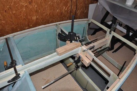
Next step was to start shaping pieces to fit to the contours. I went in order from F22 to IP then to the seatback since the seat was getting moved back an inch and might throw off some of the dimensions (I think the fuselage gets a little more narrow as you move back at that point). The IP took a few adjustments, but not many. I made special blocks that were slotted so that I could fit a clamp onto it in order to pull the side and the IP together. I also added a board to the table to position the top of the IP in the right spot. Placement lines were drawn on the lower longerons so I knew where to align the pieces. Marks were added to the side of the fuselage to show the placement of the piece.
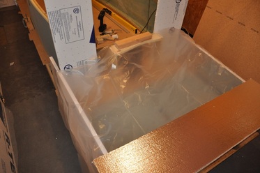
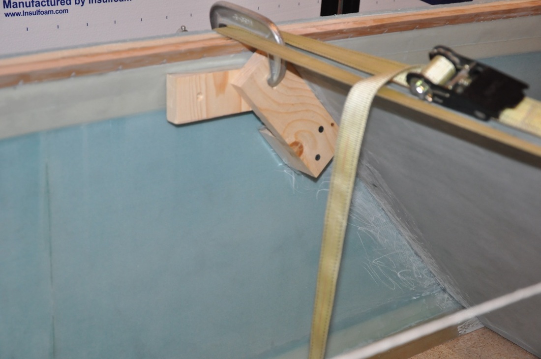
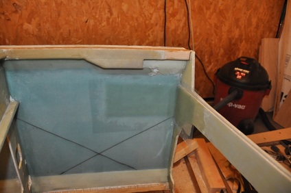
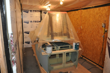
The seatback was harder to deal with. First I positioned the top of the seat so that it was 1 inch behind the plans position. This was something that many people recommended doing, and since I'm rather long legged it made sense to do. I tried to follow the template for cutting the correct angles out, but the compound curves were rather difficult. I used a carpenter contour guide to get the shape that was needed for the seat. Several trials of fitting, measuring, trimming, and cycling back the seat was mostly in position. However, I found out that my seatback warped sometime after making it months ago so one side is not sitting where it should be. So this will need to be fixed. A suggestion by Marc Z (thanks Marc!) was to heat it hot enough to soften the epoxy, then weigh it down flat and let it cool slowly. This will hopefully lock it back into shape, so that was the next task. So I built a small insulated heat tent with leftover foam board from making the room and some plastic to cover the top. I elevated the seatback onto small pieces of 2x4 to allow heat to circulated all around. The heater was set to high and allowed to oscillate in order to better distribute heat. A temp probe was added below the seat (the area that would get to temp the slowest) and an alarm set for 140F. It took about 1-2 hours for the temp to reach this level, at which point the tent and 2x4 were removed as fast as possible, the part was set down on the table top, and a second piece of table top added on top of that with as much weight as I could find to distribute to press it into shape. This was left for about 2 days before removing and checking. A bit of warp came out. It fits slightly better, but I'm starting to realize I may also have a slight slope in the bottom edge. I may not have cut straight at some point. The problem is small enough that I think I'll assemble as is and just make the spacers for the bottom of the fuselage take up the space. I'd rather do that than possibly adding twist to the structure.
So I set up a heat tent with a thermometer and heated the part till I reached 140 F at the coldest area. Once that occurred, I quickly removed the tent, laid a piece of table top material I had left over, then proceeded to weigh it down with everything I could. This was left to cool overnight. The next day I checked the part and I think I got some of the twist out, but not all. Mostly it wasn't twisted but rather bowed in towards the center slight. It didn't look like it was going to get better without some serious heat. So the fitting continued knowing this would throw off things a bit later, but should be recoverable. .
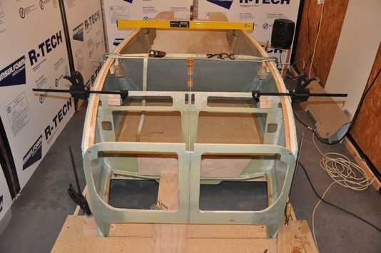
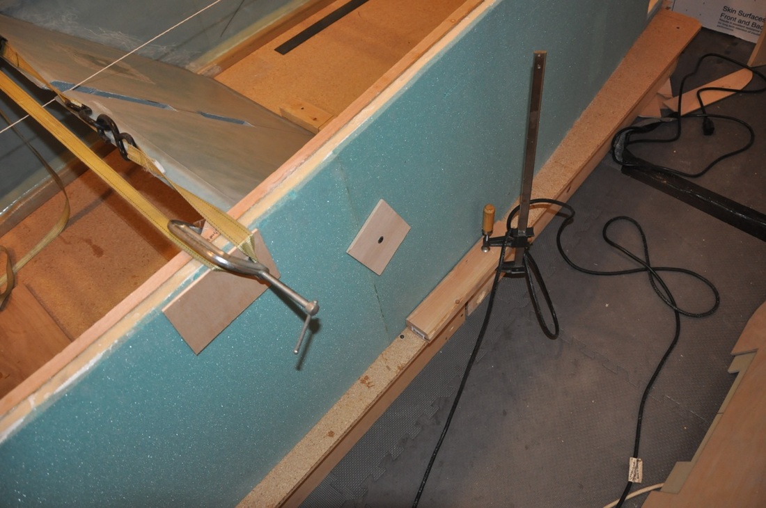
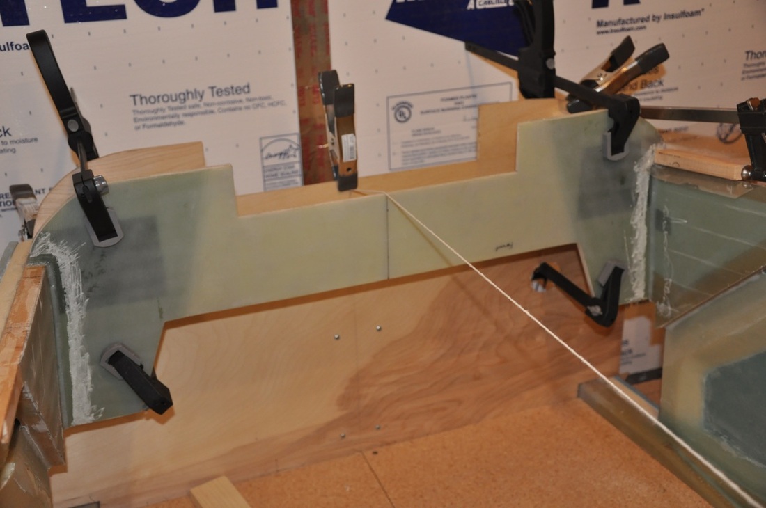
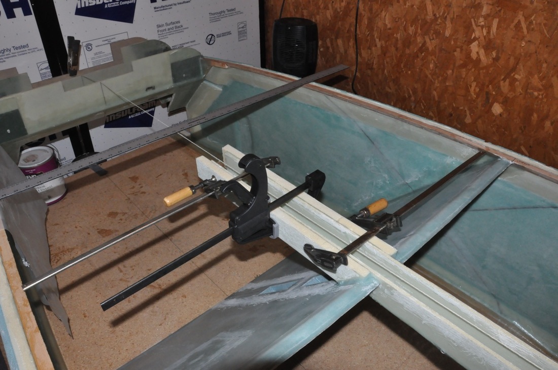
After wrestling with the seat, more fitting took place. There still seemed to be some twisting action going on, so I recheck all the alignments. Not happy with being unable to fully verify the top alignment, I screwed down a piece of twine to the table right on the centerline at F22, ran it up the centerline of F22 then went across the fuselage to the firewall where I clampled it in place on the center line on the firewall. I know that these two were vertical and centered, so they would be used to verify my other marks. The IP lined right up, as expected. What was this? The seatback, though lined up at the bottom, was slightly crooked at the top. I must have over trimmed one corner. I straightened the seat back so the centerline was matched on both top and bottom. Guess what? The sides fitted with little issue. It only took mild clamping strength to pull things in and the one side didn't twist up! Amazing what happens when things are where they're suppose to be. Only thing this will cause is that the top of the seat back will not be level. I must have accidentally cut it at a slight angle somehow. This should be okay since you cover up the top with the headrest platform anyway. So with that out of the way, fitment was verified, large gaps were filled in with foam.
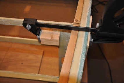
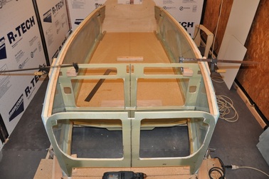
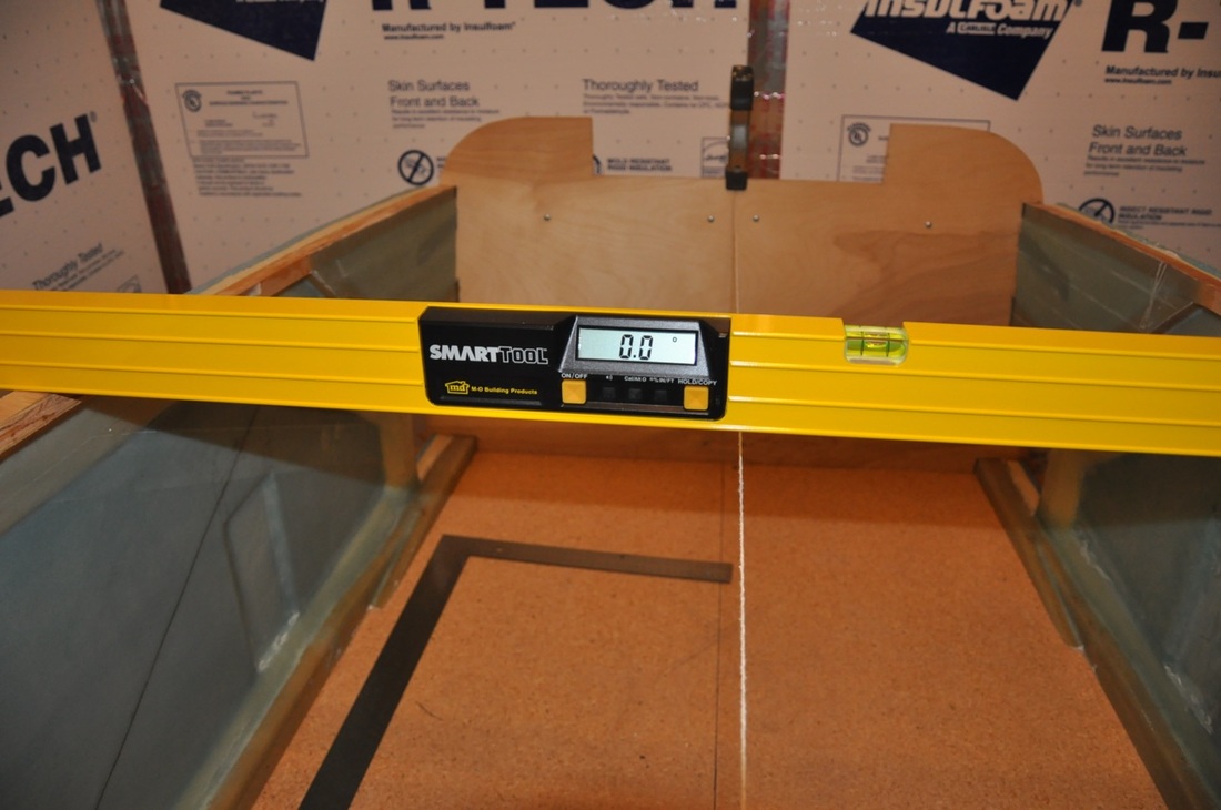
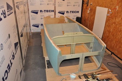
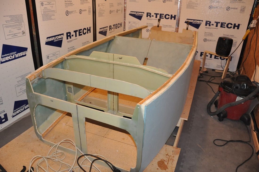
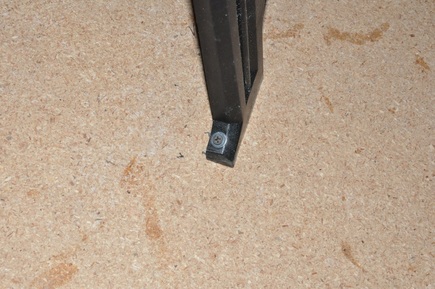
To push the sides in, I used my custom blocks on the IP to pull the sides to it and used blocks to push the bottom in. The center didn't need anything. I also used some plywood to make placement blocks to hold the IP to the right position at the table top. The seatback has two custom blocks to clamp rest against at the proper angle. Stop blocks were added to the base to push the sides up against the seatback. I used one drywall screw through a piece of 1/4 inch plywood to push the center of the sides against the seatback edge. I don't think it really needed it as it was fitting rather tightly, but it will help to hold it in place. I screwed F22 to the longerons rather than use nails as they are easier to remove and could be removed and inserted multiple times and retain grabbing strength. This this done, I unclamped one side to see what the structure would do. It bowed out slightly at the seatback where there was nothing holding it against the seat, but the structure didn't twist. If I had screwed that area to the seatback, it wouldn't have moved at all, so I considered that good enough to commence with gluing. All bulkhead positions were confirmed to be vertical to within 90.0 ± 0.1 degrees. The seatback was at 47 degrees (similar to what others have seen). Side to side comparison at the lower longerons were anywhere from 0.0 to 0.3 degrees. The area that was 0.3 degrees was due to the longeron gluing at a slight angle rather than flat. It looks like a clamp moved a bit and didn't hold it flat, but was hard to see until comparing to the other side. A slight shimming with foam when the bottom is made will allow the bottom to be level later on. So it's not a perfect craft (already wasn't perfect before), but I'm pretty sure it qualifies as good enough to continue.

So the big day arrived where I committed the fitment to gluing. I undid the clamps, spread out the sides as suggested in the plans, and mixed up some flox. About 60-80 grams worth of epoxy allowed me to do the seatback which required the most since it's thicker. The IP and F22 were done with around 40 grams each. I used a plastic sandwich bag with a corner clipped and laid down a bead of flox along the sides of the fuselage and along the mating edge of each bulkhead. The pieces were pushed together, clamped into place, then the excess flox was scraped out using the mixing stick. I tried to create a nice rounded fillet with the stirring stick but found my gloved finger worked better. Don't want to leave much on, but wanted to round the corner enough to aid in BID taping later. Also made sure to remove flox from any open areas such as the rudder conduit, torque tube cutouts, and the lower openings on the IP sidesOnce all the excess was scraped away, another hour was spent verifying everything was where it should be. F22, temporary firewall (which was not glued) and the IP were at 89.9 - 90.0 degrees. The seatback was 46.9 degrees. This appears to be about 0.7 degrees less than it should be. I think it's from the warp issues I had, but I'm pretty sure this will still be fine. We'll just be slightly more reclined. Side to side heights were still 0.0 - 0.3 degress, the same as before, so all good there. One last check of all the joints and the shop was closed up for the evening never to be seen again till 24 hours later (so says the plans). The temperature was maintained at 75 - 80 F for the entire night to avoid large changes.
After cure, all the clamps were removed. To my delight, nothing moved when unclamped! All angles were checked again with the smart level to see if any movement took place. Here's what I got for angle degrees:
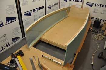
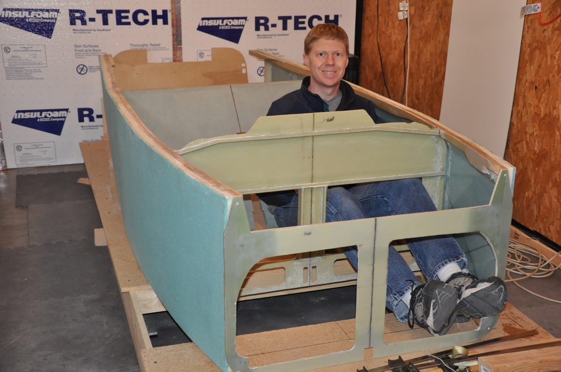
While not perfect, it should be within the expectations of the build (Nat didn't have a smart level, so I don't know how close he could get, though he probably is still better than me in a lot of regards). The lower longeron issue will be easily fixed with some extra foam on the lower side to bring the bottom back to level when I get to that part, so I'm not worried about it. The seatback is no big issue other than I have to adjust for the different angle when making the seat brace, however, it sounds like I have to do that anyway. I think the seatback is one piece that can have some issues and be okay since it's the first part you make. I'm still connected across the plane so I should be in good shape. Of course, I couldn't resist the urge to take a test sit in the structure.
- F22 - 89.9 (should be 90.0)
- IP - 90.0 (should be 90.0)
- Seatback - 49.9 to 47.3 (should be 47.6) Still had some warp in the part
- Lower longerons (measurement across the top) - 0.0 to 0.3 (area near F22 didn't remain flat to the foam on one side)
While not perfect, it should be within the expectations of the build (Nat didn't have a smart level, so I don't know how close he could get, though he probably is still better than me in a lot of regards). The lower longeron issue will be easily fixed with some extra foam on the lower side to bring the bottom back to level when I get to that part, so I'm not worried about it. The seatback is no big issue other than I have to adjust for the different angle when making the seat brace, however, it sounds like I have to do that anyway. I think the seatback is one piece that can have some issues and be okay since it's the first part you make. I'm still connected across the plane so I should be in good shape. Of course, I couldn't resist the urge to take a test sit in the structure.
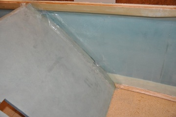
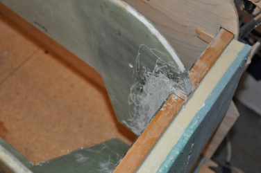
Next up comes the BID taping. First item is to sand the joint area for a good bond. I never could get sand paper to hold up well. I then discovered a neat attachment for the fein. This was a wedge with carbide grit permanently fused to the surface. With this and some light pressure and constant moving, I could sand and roughen an area including the flox itself in relatively short order. I can go overboard with this tool, so proceed with caution. Once roughened, vacuum up all the dust and prep the BID tapes. This involves cutting 2 inch wide strips of BID cloth at a 45 degree angle and applying two plies to each joint. There's 10 joints total for this round: 2 on F22 (aft side only), 4 on the IP, and 4 on the seatback. I cut out sheets of my mylar, laid the glass strips on the surface, spread out the epoxy, wetted out the glass, then placed another sheet of plastic over the top to squeeze the excess epoxy and air out, then cut the plastic and glass to length, carried over to the joint, wetted out the joint with epoxy, peeled one side and placed the glass in and remove the other side. Then you remove any air with stippling, peel ply the joint and squeege out excess epoxy. It sounds like a lot, but it's not too bad. Unfortunately, I was running low on peel ply for some of my joints, so I used plastic to dress up the joints knowing I would have to sand later for any other layups. Once cured, the tapes were trimmed and checked for any issues. All looked good, so now the structure is nice and stiff.
Another important layup at this time is the 4-ply BID that goes on F22 to re-enforce the canard attachment. This was done by wetting glass out on plastic, covering with a marked sheet of plastic with dimensions for the piece, excess epoxy and as much air worked out of the layup, then cut to size. Then you have a nice package that can be taken over to the layup area where it was previously sanded, wetted out, then one sheet of plastic peeled away and the plies are pressed into place and the air worked out. The other piece of plastic is then taken off. The directions say to use peel ply here to make the edges nice. I decided to do plastic peel ply to work out as much air as possible and to get the smooth edges. That new fein tool attachment has really decreased the amount of time I have to sand that I'm okay with having to sand edges later for the benefit of getting what should be lighter layups with less trapped air specs. The smoother texture will work out well when finishing work comes around as I don't have weave to fill in or a rough texture to deal with. After cure, the excess was trimmed from the layup.
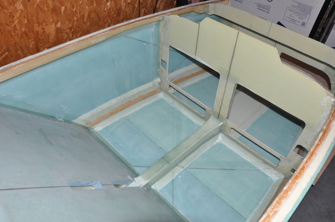
F28 was then installed onto the fuselage. The trick here is the realize that the distance (which was changed from 5.9 to 6.25 inches) is done from the front side of F22 to the front side of F28. The other thing is to realize that the ends of F-28 are thicker because of the extra layups that were done there. So just pay attention to what part you're measuring when setting this up. I set up a block of wood clamped to the table opening to act as a placeholder for F28 and to clamp it to in order to retain vertical alignment. I did have to trim F28 a bit to fit. This appears to be normal and may have to do with the fact that the seat is moved back 1 inch. 1 inch forward would spread the sides slightly more. At any rate, others have had to do this as well. Once floxed in place, the aft side only was BID taped. The forward side will be cut away for the canard installation later.
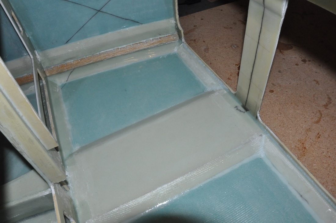
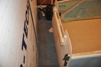
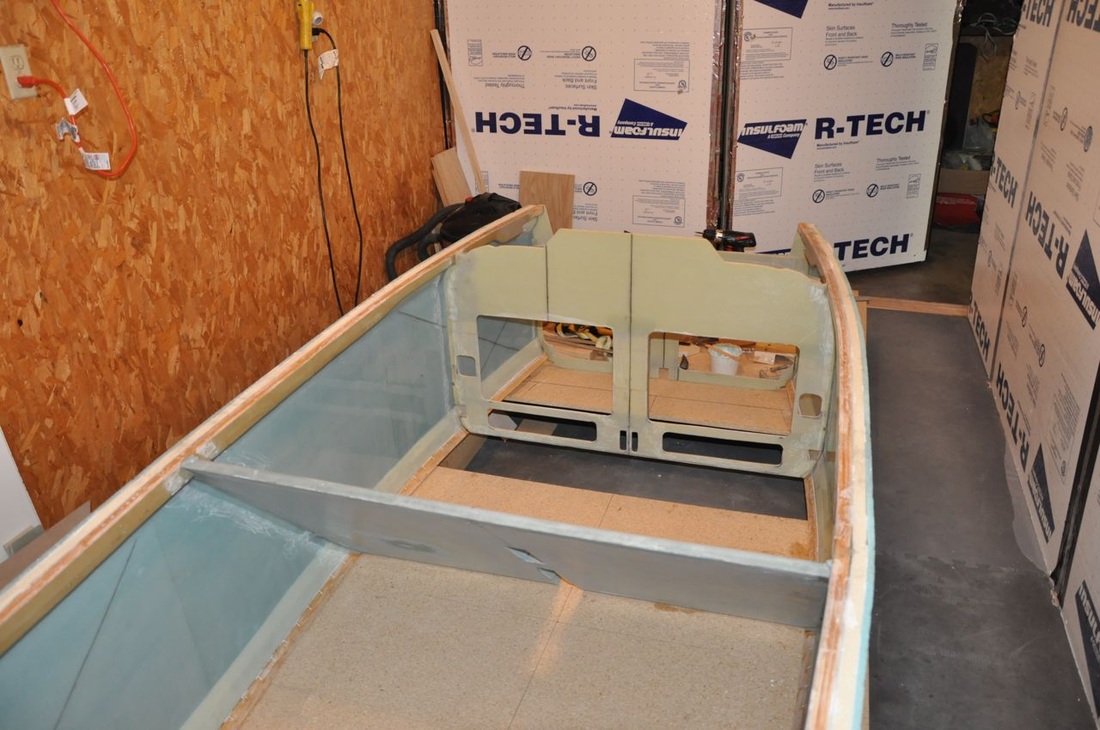
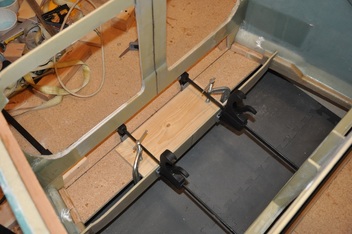
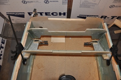
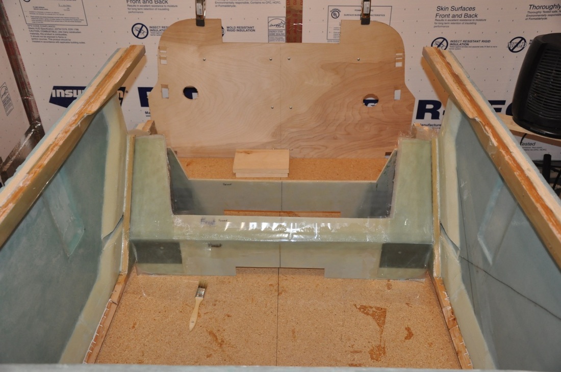
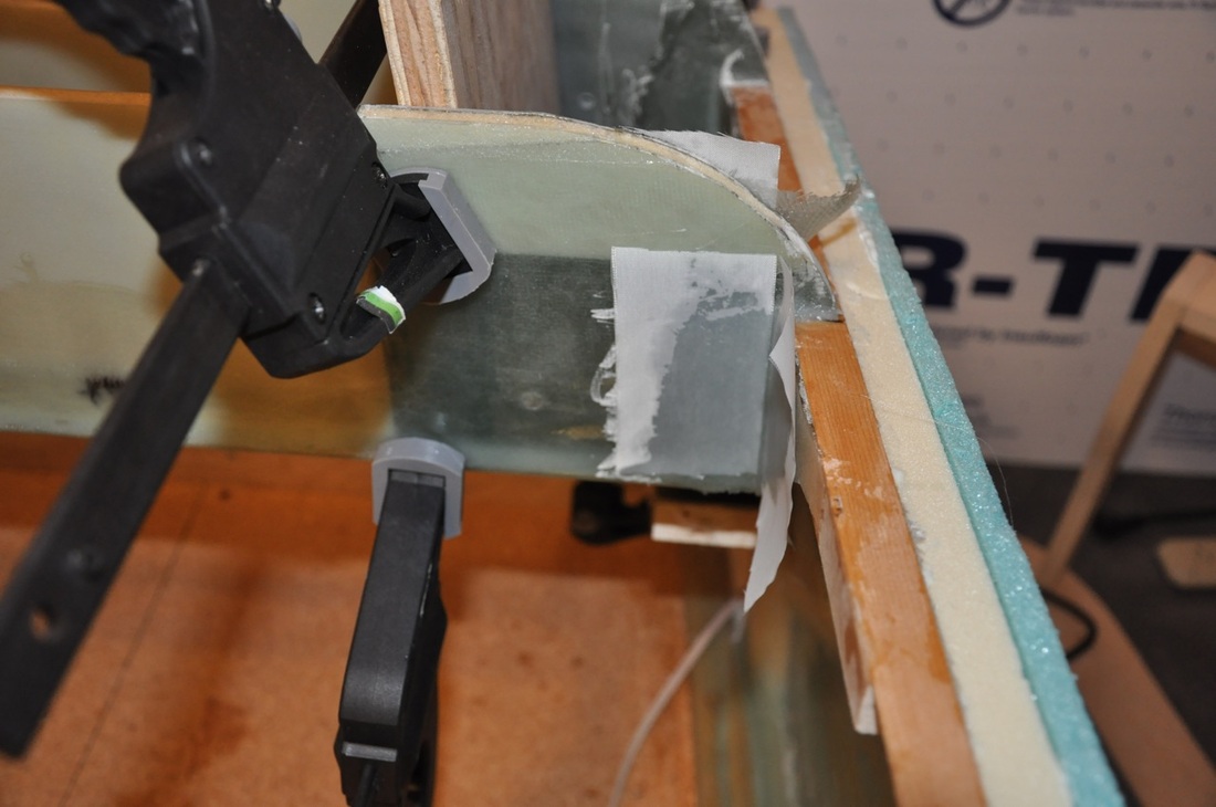
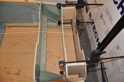
Next came the installation of the landing gear bulkheads. The temporary firewall is still used for this and it was adjusted to make sure it was vertical before continuing. Blocks with a 5 inch length were cut to position the aft landing gear bulkhead and 8 inch blocks were used for the front landing gear bulkhead (lower portion). Due to the extra layups on the bulkheads, the edges will be thicker than the center. Since the gear bolt to the edges, I positioned the blocks to guide off of the edge area for the position. For the aft piece, I just test fitted, sanded all the mating surfaces, then floxed the edges and placed the blocks in to be clamped in place. Turns out that the bump I had in the electrical outlet area wasn't a big issue and I just had some minor gaps to fill with flox. Make sure the spacer blocks aren't near any of the flox material to avoid gluing your blocks to the piece. The flox was rounded in the corners to facilitate BID taping after cure. Once cured, the blocks were removed. Make sure you flox the correct face forward as there are different sides. Remember that the side with the greater number of layups on the ends goes forward.
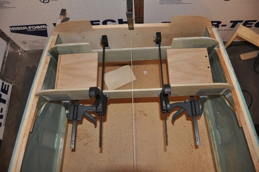
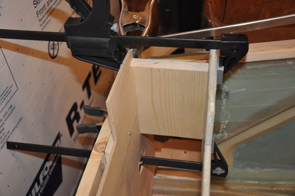
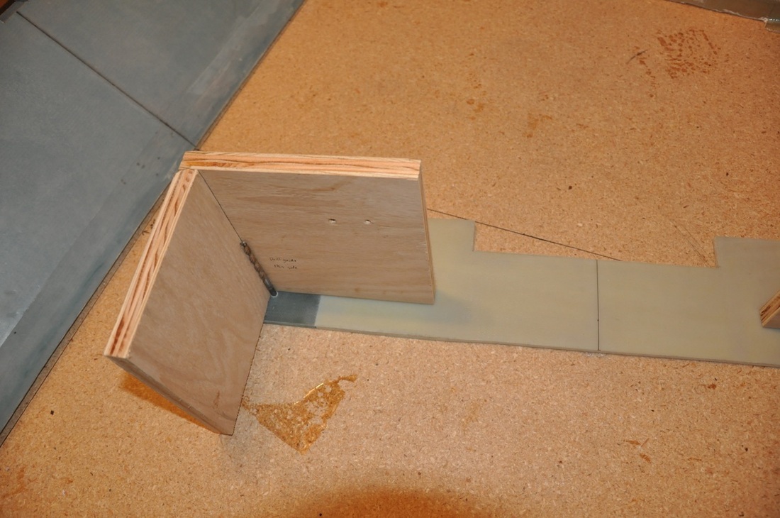
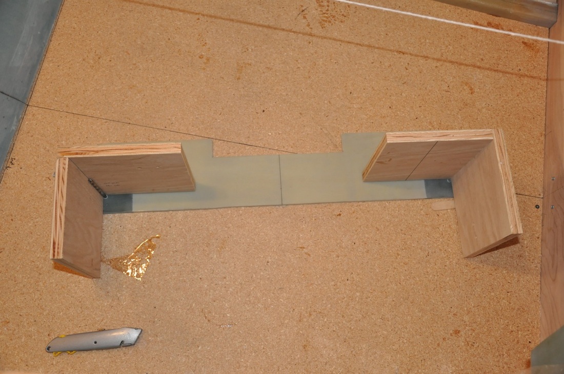
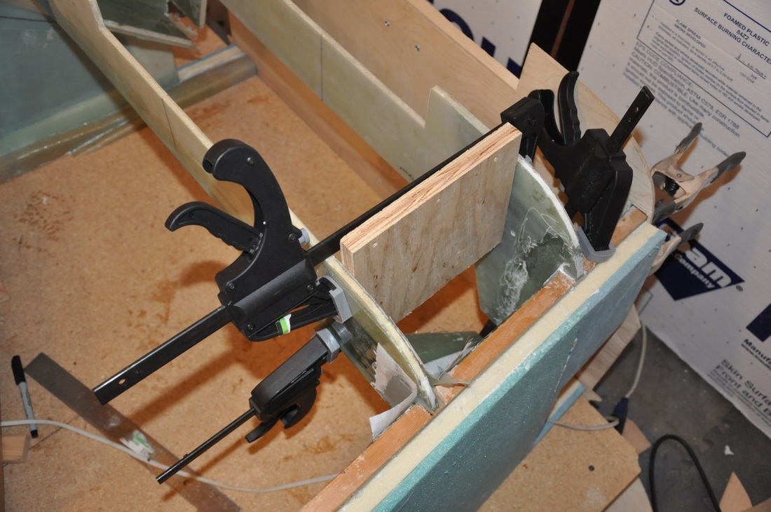
The forward bulkhead has a different treatment. Four blocks were cut that were 8 inches long. I decided to use 0.75 inch thick wood for this to get a beefier structure to clamp to. Two sets of two pieces are connected at a 90 degree angle that is then positioned on the predrilled hole. A drill bit can be used to align the pieces. They are then hot glued into place to hold that position. This also gets clamped into place ensuring the bulkhead is vertical and the correct width from the other. As before, the edges get floxed and allowed to cure. After cure, a 12 inch long 1/4" drill bit is used to drill the hole in the aft landing gear bulkhead by using the wood spacers as a guild. I used a gloved finger to ensure the bit remained aligned in the wood spacer corner. After that, the spacers are knocked out with a rubber mallet and any residual glue was removed. I decided to go ahead and flox the upper portion of the bulkhead in place before doing the BID taping so that I could do the tape as one piece. Plus it'll be easier to BID tape the up-side with the fuselage flipped over (since it's still upside down at this point). So I used some clamps and a mailing tape covered piece of wood on either side to hold the piece flush with the LWX wood stringer. I checked the clamping fit, sanded all the surfaces with the fein tool, then buttered up the edges with flox and clamped together. The excess was removed while rounding the corners for easier layups later. After cure, one of my blocks was a bit stuck. After removing with a rubber mallet, I found a bit of wood stuck to the upper part where the epoxy spread past the tape. This will sand off easily.
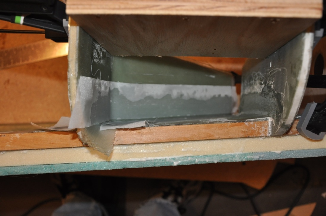
Next comes all the taping and additional layups on the landing gear bulkheads. While the fuselage is upside down, I did the internal layups as it was easy to get to. All the surfaces were re-sanded using the fein, then the BID taping of the side joints and the joint between the upper and lower portion were done. Next came the UND re-enforcement layup on the sides of the bulkhead. Since the fuselage was upside down, I decided to do the aft side layup first. I followed Bernard Siu's example and made a rectangular stack of UNI (6 plies in this case), wetted out the glass, then I used a piece of plastic where I had drawn the shape and size of the layup on. The pieces have one right angle and one acute angle so that if you flip one and put them together they make a rectangle with an off center diagonal. You can then cut both sides out and you have pieces ready to lay up. Keep in mind that the fiber orientation follows the slanted side, so when you cut the pieces, the outside of the original rectangle will be the edge that follows the slanted side of the bulkhead. I made mine slightly longer so I could trim to fit. This was pressed into place, the air worked out, and the layup peel plied. You want to roughen these layups as there will be more layups in the future. After trimming, the fuselage was flipped over to do the BID taping and re-enforcement layups on the other side.

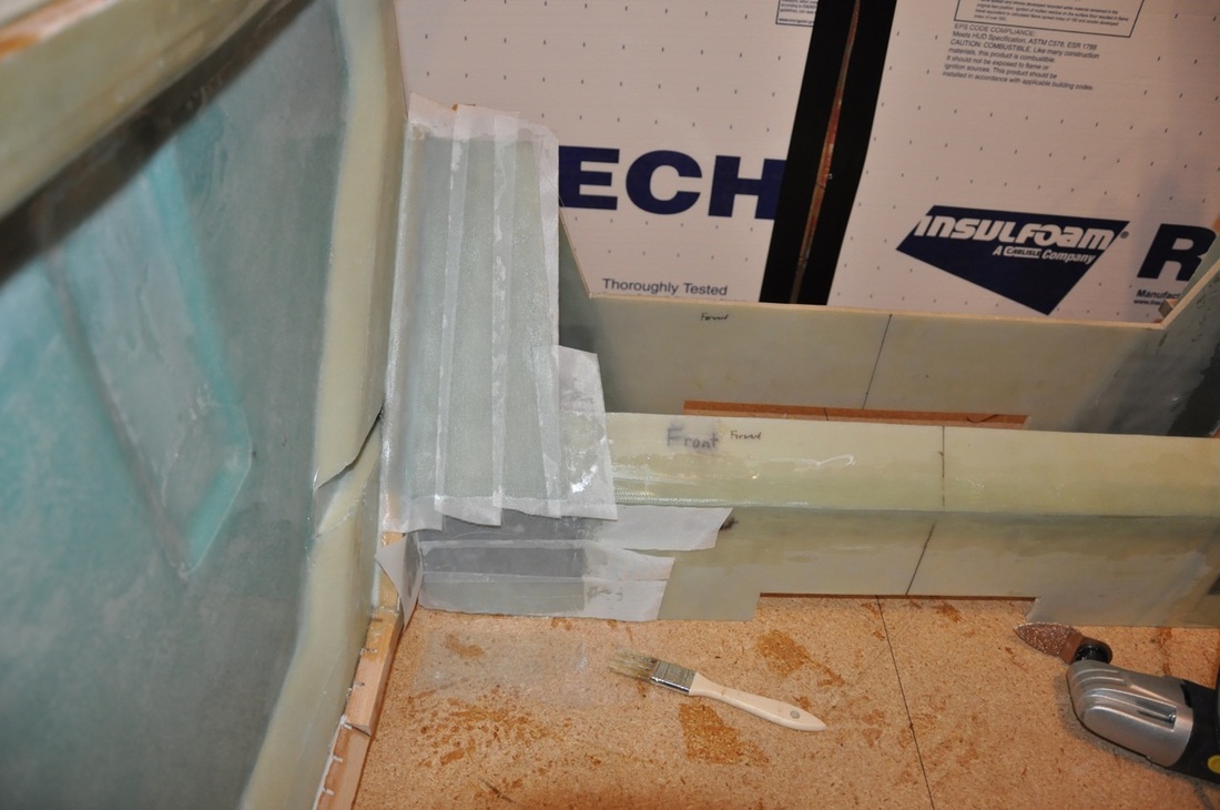
Well, as they say, building an airplane is for a learning experience and I'm certainly learning. The Forward landing gear bulkhead just didn't seem right. Checking measurements, I could tell something was wrong, but couldn't quite tell where. Finally, I found a straight piece of oak board that I clamped to the aft of F22 that gave me a nice solid straight line reference from the aft side of F22 to measure everything on. I checked the left and right side of all my bulkheads. The IP was off from perpendicular by 1/16 of an inch (deemed inconsequential and left alone), the seatback was perfect, but the landing gear bulkheads were both 0.25 inches farther back on the right side. Somehow my firewall reference got off and I didn't know this until I was already taped into position. If I had to do it over again, I think I would use a 1/2 inch piece of plywood as it would be naturally more stiff and straight. I thought about posting to the group, but decided that I knew what needed to be done. The joint was just a flox joint with BID taping on it, so cutting out the joint, and floxing and BID taping it to the correct location seemed like the best option. A quarter of an inch was small enough that the bulkheads could be pushed into place without affecting the shape of the fuselage much. I made sure to generously pack the small gap with flox when reattaching the bulkhead and used a light to check for voids. I went ahead and BID taped at the same time just to save time and sanding though I had to maneuver around the clamps and spacer. I managed to tape the joints just fine. Placement and were rechecked: they are now perpendicular to the center line and are within 0.1 degrees of vertical. Only problem is that the angled side of the upper forward part is now no longer completely flush with the LWX stringer near the lower bulkhead, but transitions to flush towards top. I'll fair in the area with the flox joint as the BID taping is done so that there shouldn't be a structural concern and will just be cosmetic. It should be fine as there will be plenty of surface to attach the BID tape to and there will be many other layers added on later. I also added one layer of UNI over the BID. It may not be necessary, but since the original BID was sandwiched between glass layers I wanted to have the same here. It may add weight, but if it makes me feel better then so be it. I did both the BID and the UNI in one round of layup then peel plied before curing. There is a small bump now in that area, but it'll be covered up with more glass and eventually seat cushions, so it'll be a non-issue.
After the repair, I turned my attention to the firewall. It's funny, but few sites show this getting installed that I wasn't sure when it happened. Anyway, you're suppose to transfer your cutouts from the temporary to the permanent so that the fit is perfect. I had trouble doing this because my temporary wasn't cut very well in profile (leftover from my firewall template issues). So I got it as close as possible, drew the lines down, then took the permanent to the fuselage and clamped it onto the ends of the longerons so I could check the alignment. Good thing as it was about 1 mm too far over to the left. I adjusted this, then I cut out the LWY stringer (large 2 inch piece). Once that was cut out, I used a file to adjust the fit and make sure that the center line lined up with the fuselage center line. Once cut I could see where the other cutouts needed to be and adjust those as well. I few times matching the piece up, cutting out wood, filing, fitting, filing, and so on till it was fitting up to the proper mark. I then floxed it to the fuselage. I read up on whether it needed BID tape (plans don't specifically say it). The comment was that so many other layers of glass go onto this piece that BID taping, though wouldn't hurt, was probably not necessary, so I chose to save some weight (I need to at this point!)
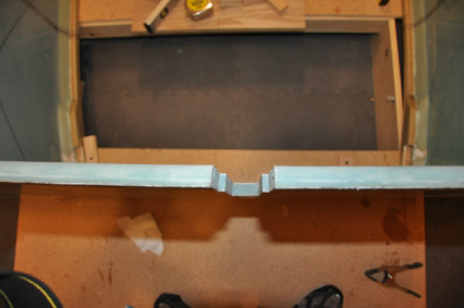
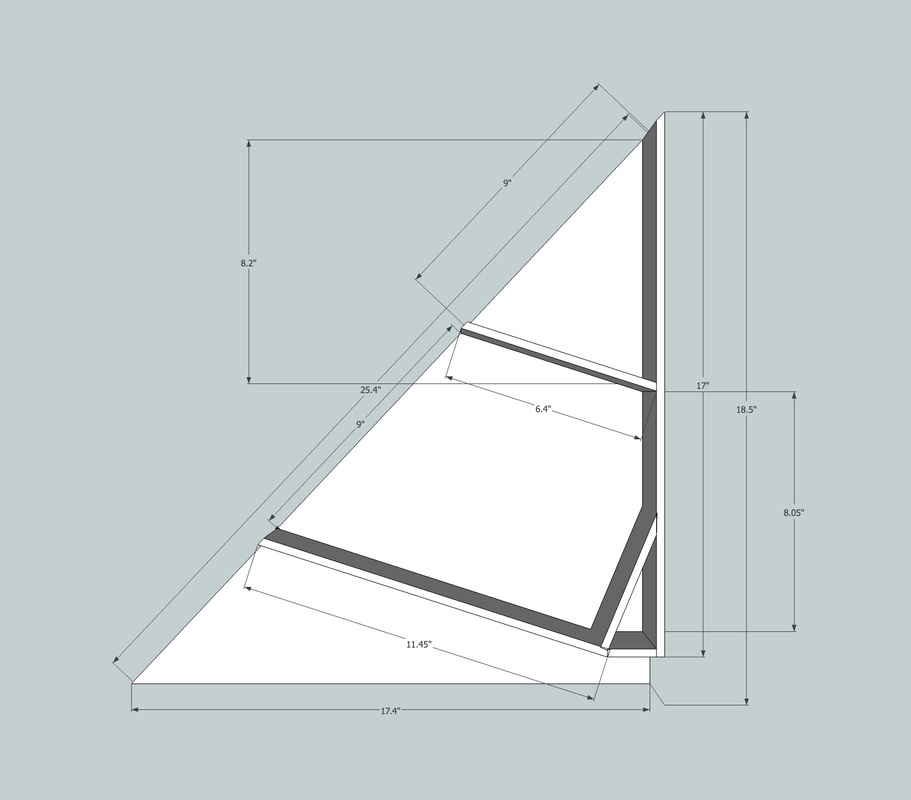
Now it's time to get back to some part creation! Next step involves making the front heat duct and seat brace. I decided that it would be useful to make it wider, 3 inches wide to be exact. This will allow standard water bottles to fit in the pocket. I've contemplated the location of drink holders and there's not a great location in the front for such a thing. This will allow for storage and only take up a bit more space in the back. One thing it will do is move the landing brake actuator over 0.75 inches. I'm going to make mine with a full length hinge so this shouldn't cause much of an issue. I will have to add 0.75 inch spacers to either side of the heat duct where the seat brace meets in order to support the brace. Not too big of a deal. There are others who run an electrical conduit up the brace. I wasn't sure how I would be able to use this due to the vertical entry point and uncertainty in how the cavity could be accessed. Since it's a structural piece, I decided not to mess with a conduit and can make some that run along the top of the seat. This will make a lot more sense for my purposes anyway. I also made the pocket bigger by raising the top 2 inches and the bottom half an inch. This gives a height of 9 inches. The 2 inch raise was done because it stops plenty before any layups for the shoulder support that is added two chapters from now. I limited the lower movement so that I had plenty of room in my conduit that's added later as well. I wanted to do something with the space where the fuel bracket goes, but decided to leave it alone. I might be able to utilize it down the road for something. I decided to go ahead and install the wood supports in order to accommodate any future ides for that spot even though the fuel valve will be moved up to the front.
I measured the angle of the seat back which was off from the plans angle. This just involved a bit of geometry to recalculate the shape of the triangles. For the spacers for the brace, they were all cut out at 3 inches wide instead of 1.5 inches. The two long spacers that form the pocket were cut longer and will be trimmed to fit. The heat duct spacers were cut according to plans with no issues. The top piece had to be cut from three different areas, so a simple hinge method to glue them together was done to make the whole piece.
Something I picked up on another builder's site was the use of an air splitter for the heat duct. Chad Baker added a spliter and larger holes to allow for more air flow. I liked the idea enough to copy it. This is a wedge shaped piece of foam that gets glued to the middle support on the heat duct outlet on the IP. He then opened up the holes to be flush with the sides of the duct to make for more air flow. The splitter helps with less turbulent air flow. It was such a simple idea that I decided to do it as well! Anything to keep it warmer in the winter or for high flying.
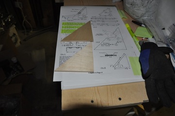
I cut the wood spacers according to the plan but without the cutouts for the fuel bracket. I just made a full triangle, then cut them from the leftover firewall plywood. Pretty simple and they look like they'll fit in with minimal sanding.
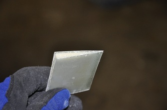
The plans says to keep in sheet form to glass, then cut out. This certainly would be easier, but I was worried about glassing opposites. There are two pieces you have to be careful about to not glass the wrong side: the seat brace triangles and the heat duct sides. The idea is you want to glass the inside area only at first. So stack your pieces together like you're assembling them, then mark the inside faces so you know which to do. I marked the wrong side of one of mine and didn't notice till after I had applied micro. Luckily I caught it in time and flipped the piece over to micro it (nope, I was right the first time. Found out later I fooled myself and ended up glassing the wrong side anyway. Must have over-thought it). I'll have to sand the other side to roughen the micro for proper adhesion later, but it shouldn't be too bad. I caught the heat duct before starting, so it's fine. The other reason I went ahead and cut pieces out was that I could use a lot of my scrap glass pieces to do the 2 ply UNI and BID layups. For the triangles, I cut the BID at 45 just for consistency sake even though the plans say orientation didn't matter. The UNI was oriented along the length of the straight pieces. I cheated a bit here and since the pieces were small, I went ahead and glassed both layers at the same time. I had been doing this for the BID tape and it worked fine. What I found was that if I got the epoxy out as soon as possible after mixing and spread it out it would soak in with little trouble. Some squeegee work and it was done. Since these areas will be difficult to get to after the piece is assembled, I plastic peel plied all the surfaces to smooth them out and remove excess air and epoxy. After cure, they turned out great! Just need to trim then move on to assembling the brace.
Next comes assembly of the brace. As before with other things, I made a Google Sketchup (poor man's CAD program) to make sure I knew dimensions and locations of pieces. This really helps to double check your logic when making a change. I forgot to add the extra length to the back spacer and found this out when designing the sketch. This allowed me to glue another piece on to get the correct length before glassing, so that saved a slight hassle. I attached both the Sketchup file and a PDF image of the brace layout for my design if anyone is curious.
| spacer.skp |
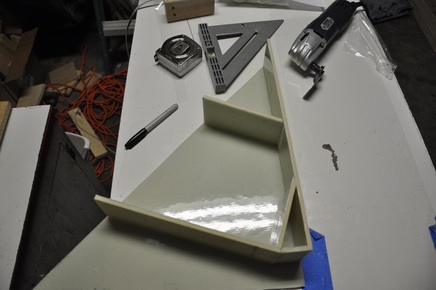
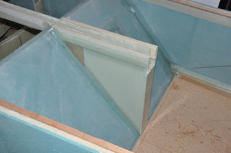
The spacers for the brace were sanded to bevel the edges to fit, then they were 5 min epoxied to each other to make it easier to deal with. I just attached each piece one at a time an was able to get them in place. Then it was trial fitted to one of the triangles. I sanded the mating areas then drew out the profile lines for positioning the spacers, then floxed them in place and weighed down for cure. I found I didn't have to use nails as once the weight was on I could move the pieces into place they remained there nicely.
Once the spacers cured, 1 ply of BID was added to the unfinished sides of the spacers overlapping onto the sides of the brace 1 inch. This helps to strengthen the piece by fully encapsulating the foam and structurally connecting the sides to the spacers. Once cured and trimmed, the other side of the brace was sanded and floxed into place. A spacer was placed in between the sides where the wood was in order to retain the proper shape while curing with weight on tom. From there it was just a matter of rounding over the foam edges on the outside where glass would cover, micro the surface, and glassing the outside with 2 ply BID at 45 degrees. One side was already done (thanks to a previous mistake), so the edge was sanded 1 inch from the edge for bonding the new glass to. There will be a slight bump there to take care of, but should be fine.
The heat duct ended up being more trouble than needed. I should have made a contoured spacer to hold the piece together. Instead I used scrap bits I had hanging around. Took a lot more effort to clamp everything (you can never have enough clamps), but it still worked. Unfortunately, I floxed the top piece to the bottom of the heat duct (the side that doesn't have the curve in it), so I had to cut it free and redo (more of that learning experience). After cure, it didn't look too bad considering the reconstructive surgery that was done.
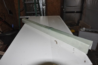
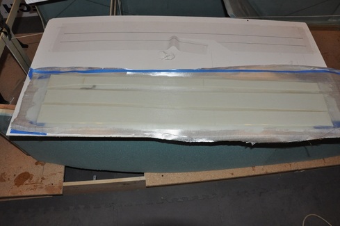
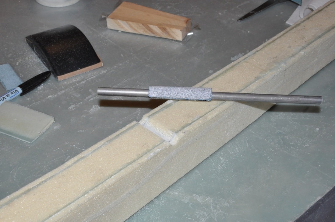
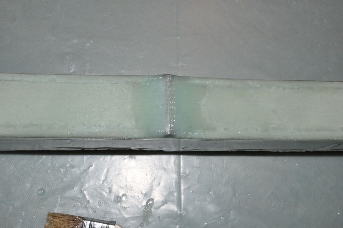
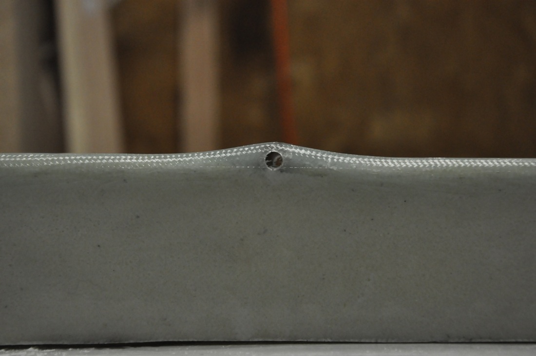
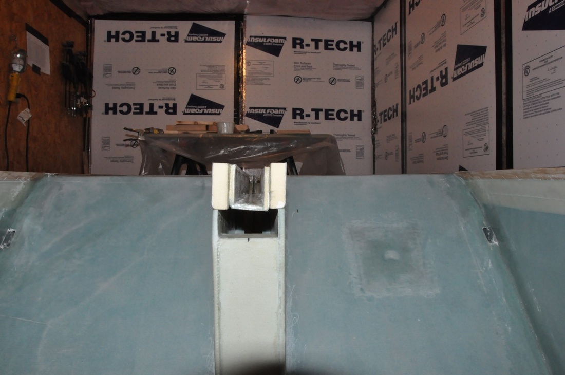
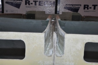
The heat duct gets a little extra prep before the 2 ply BID goes on. First, I used a piece of the aluminum tubing for the seatbelt attachment to wrap a piece of sandpaper around for sanding the groove. The groove gets sanded down the fiberglass layer underneath (but not through the glass). I then cut a piece of the tubing and sanded the outside to clean it up and roughen the surface for better adhesion. Before glassing, I set a 2x4 on the narrow edge and covered the top with plastic. This suspended the piece so the glass could hang off the bottom straight. Flox was mixed up moderately stiff in order to use the smoothing technique Bernard Siu illustrates. First, micro the foam, then lay out the flox and press the tube in place and fill any gaps as well as add a generous fillet of flox to the sides. UNI does not like non-gradual contours. The 7-ply UNI was done using the plans method. It mostly worked, though I still got some stringers. However, you do get the nice tapered appearance. I drew out the 2 inch width on plastic and used that as the gauge for where to cut. It was then sealed up in between plastic layers like BID taping and cut to shape before transferring to the duct. Extra epoxy was used for the tube area to help wet out the dry flox in order to smooth it out and make a nice transition for the glass. Once the UNI was applied, the entire piece was covered with 2-ply of BID at a 45 degree. After cure, the piece was trimmed and the tubing hole was opened up with a 1/4 inch drill. I found that if I went slow on the drill press with the drill mostly centered and kept a loose hold on the piece, the drill would naturally center into the hole as the fiberglass was much easier to drill than the aluminum. I got perfect holes this way.
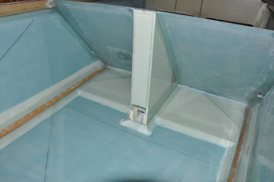
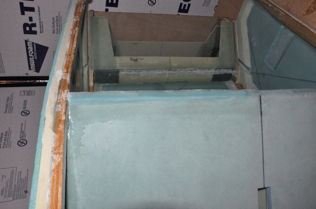
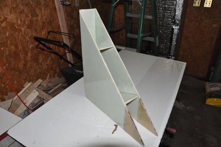
I decided to follow Bernard Siu again and install the heat duct and brace separately. Part of the reason is that I'll have to add spacers to the sides of the heat duct to make up for the wider brace. These spacers were made from 3/4 inch foam (same type as the duct) and shaped to fit the brace profile. They were glassed with 2-ply BID on the sides that will be exposed with installed. I will BID tape the top joint since this seems like a wise idea. The brace can now sit on top as intended. I didn't have to do much to shape it to fit the seat as I had already changed the angle to match the seat profile. First the heat duct was fitted and leveled with the fuselage. I used a plastic covered 2x4 as a support for the heat duct at the IP end. I marked the center at both openings of the heat duct for alignment. Levelness (is that a word?) was verified off the bottom edges (the ones that will get attached to the bottom of the fuselage) using the Smart Level. If you use the top of the duct itself, it'll be wrong since it's sloped over most of the surface. Once verified, the mating areas were marked along with the seat angle, the needed areas were sanded for bonding and taping, and then the part was floxed into place. The spacers for the extra wide seat brace were also floxed in place at this time. I had to move one of my spacers up a bit because the duct had some twist in it at one end. Considering that the spacer is going to taped to the bottom and the brace, this shouldn't pose a problem for structure since the forces are still tied into the seatbrace from the spacers. I did discover that I forgot to make the heat duct 1 inch longer from moving the seatback 1 inch aft, but I should be able to correct this in chapter 8 then the rest is made. After the flox cured, I decided to flip the fuselage right side up as it would be easier to install the brace that way. It was trimmed to fit, then floxed in place. I had to get creative with my "clamping" efforts to hold it in position. After cure, it looked decent. The air splitter is now in place and looking good! The level indicated vertical alignment of the brace, so it's off to tape the joints now.
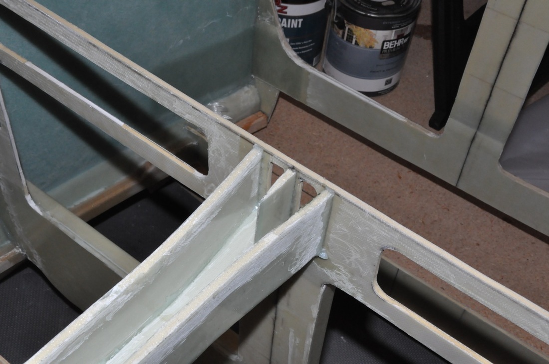
As with all other joint tapings, the area was sanded where the flox smoothed out the surface, then 2 ply BID was laid out on the table and cut to size. I went ahead and also taped the heat duct joints. Not much to it at this point. It's really starting to take shape now.
Before adding the bottom to the fuselage, this is the time to widen the holes for the heat duct. I too want to make sure there's plenty of air flow. So I enlarged the holes to max opening using a flush trim bit on my router. There won't be room to get in there once the bottom is on, so this works well. The flat surface of the IP gives the router a good base and the flush bit will follow the internal contours to match the hole with the sides. I went ahead and cut off the bottom area as this will get closed in by the bottom when it's installed. Since the bottom gets floxed to the entire bottom and the heat duct is BID taped to the IP, it should be strong enough to be fine without this little area. This should help on those cold days. I know, the work wasn't my straightest, but it's internal and won't be seen so shouldn't be a problem. So much for a perfect plane...
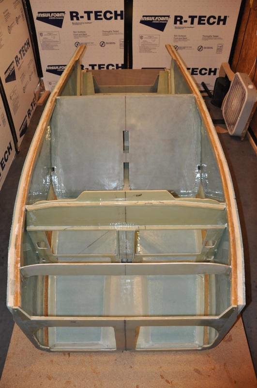
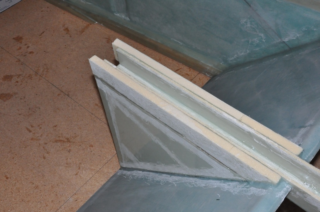
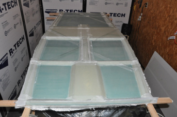
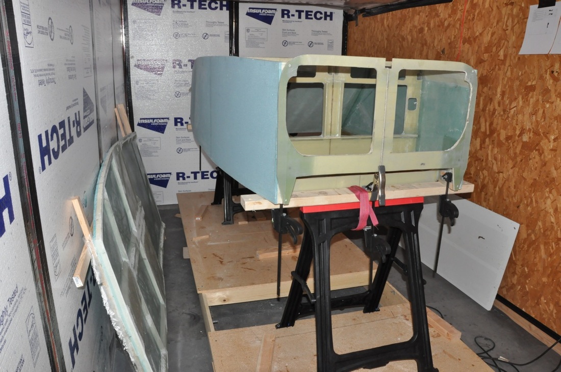
So now comes the time I've been waiting for: the last piece for chapter 6. Unfortunately, it's a large one. This section will now add the bottom to our boat and will really add detail to the structure. It's constructed very similarly as the sides were. First the fuselage was placed up on saw horses. I both clamped the plane to the boards and strapped the board to the saw horse to avoid things falling. After some shimming to level it, the 3/8" PVC sheets were laid out on top of the bottom. One piece is trimmed to fit the length, then I crawled inside to trace out the the outline of the bottom where things contact. This makes both the trimming lines and the spacer guides. After tracing, a new outside line is drawn 0.75 inches from the lower longeron lines. I used a small piece of wood that was 0.75 inches thick to off set the line. I used the table saw to trim the foam mostly because it was easy and quick. The foam edge will be cut off during chapter 7 so if it isn't perfectly smooth it doesn't matter. The foam was then glued together using 5 min epoxy ( about 5 grams of each component per joint) using the hinge method and a plastic bag piper. Once glued, it was placed back on the plane, lined up with the wooden longeron, and the inside marks rechecked. All look good, so on to the frame.
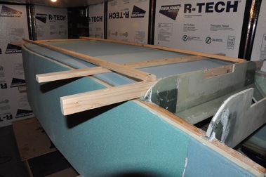
I used a set of 1 x 2 inch wood strips to create the bottom frame. Instead of gluing, I used dry wall screws to hold things. This allows for less gouges in the foam when the frame is later removed. Worked for Wayne Hicks, so it's good enough for me. Just use enough of them because it will get considerably heavier later. I had to get some thinner wood to shim the one area up front to ensure there was enough support for the curve. Once everything was in place, this was removed.
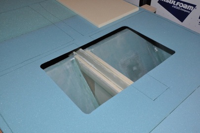
The air brake has to be cut out prior to installing the spacers since the spacer will cover up the area. I used a standard jig saw blade to cut this out. The gap left by the blade should accommodate the extra thickness added on by the glass that will go over the area. I drew out the outline for the brake as well as laid out straight edges. The jig saw was set to a 45 degree angle to make the beveled cut. I also followed the wishes of several builders and cut the brake as one full rectangle without the hinge part. Easier and quicker. Cutting was done by using the straight edges, then going slow when getting to the rounded corners. I also made the hinge mostly full length to better support the brake. The foam was carefully stored to keep it flat till needed later.
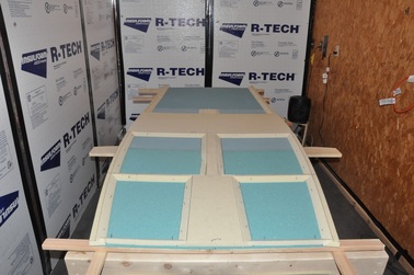
Using the bulkhead layout, spacers are carved and fitted to match the image in the plans. These are made of the 3/4" clark foam just as the sides were done. the angles were cut using the table saw again. All corners were rounded to facilitate fiberglass laying down across the spacers. Adjustments were made to fit the wider brace and the farther aft seatback. I used finishing nails to tack the spacers to the bottom in order to trial fit the part to the fuselage in order to check alignment. I had to make a couple of adjustments before finalizing the location.
Once all locations were set and marked, the spacers were set in place using micro. Finishing nails inserted at alternating directions were used to help secure the pieces in place. I put a plastic cover in place to allow the micro to cure in good time. Once cured, the nails were removed and any final sanding was done including rounding over the front edge.
To prep for the glassing, I drew guide lines to show the glass edge orientation so I would get the 45 degree angle and relative placement of the glass. I pushed the glass into the corners, then trimmed leaving plenty of excess (heard this before...). For the third piece, I kept it at a 45 degree fiber orientation just like the previous and I covered an inch onto the spacer covering the air brake and back far enough to cover the area the back seat would step in. I figured I didn't need to cover the entire back since I was already over weight and wanted to save some weight. The glass was rolled up and tagged with placement order.
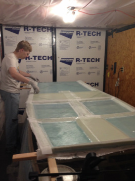
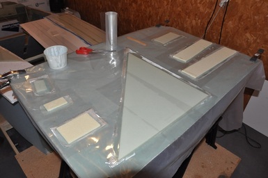
Glassing day came. I enlisted the help of a new builder, Max, and his son so they could get some experience with this before starting on their project. We used micro that was more on the dry side but still flowed and applied to the entire foam surface. Stiff micro was made and applied with a sandwich bag to all corners to help round out for the glass to lay better. We started applying the first layer of BID and despite the generous extra the glass seemed to shrink again (this seems to happen too often). Some fighting with it and we got it in place. We layed out the first layer, cut the selvege off, then wetted the first layer with 1:1 slow and fast hardened epoxy. The second layer also struggled to sit right, but eventually we got it on. The third layer was then applied. Small bubbles started to develop and some serious stippling took place. Peel ply was added everywhere that flox and BID tape would go and more stippling was done till the point was reach where the epoxy was too hard to do any good. We managed to glass in three hours on the large surface, which I think is a good time for that size.
After cure, the piece wasn't as perfect as I had hoped for. There were some small bubbles (not outside the inspection criteria) and the fibers weren't as straight as they could be. However, the piece was passable. I want it to be perfect, but will have to settle for good enough. At any rate, considering the struggles it came out fine. I did fill in a few bubbles that were big enough to require it. The peel ply didn't stay down in all places, so there was some sanding that had to be done. All mating surfaces were checked to make sure they were rough enough for further bonding. With that, the bottom was ready to glue on. A trial fit showed that it was bowed up in the center some. I'll probably remove the frame when it's in place to allow it to flex better, then cover it with serious weight.
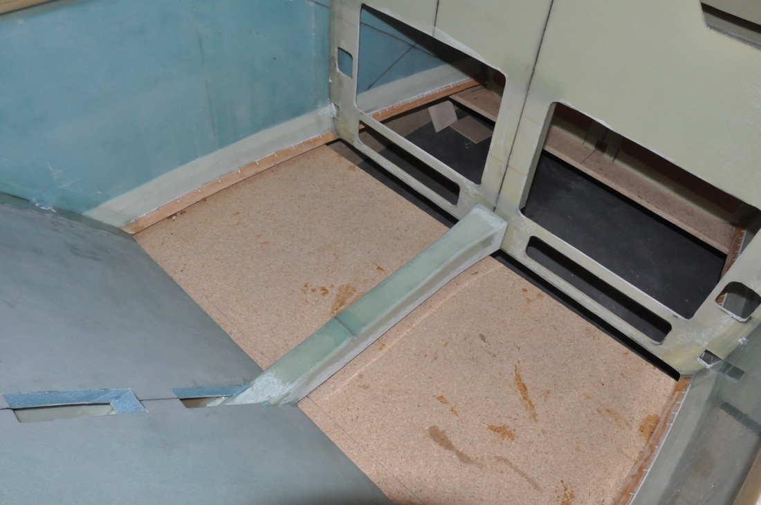
Next the fuselage needed to be placed on the saw horses so that it could be accessed from within to scrap out excess flox. This also allows the fuselage to be leveled in prep for the bottom attachment. The saw horses were screwed to the floor to prevent movement and the fuselage was clamped to the saw horses. A board was clamped to the forward landing gear bulkhead 0.25 inches below the scoop cutout so the foam would be 1/8 inch above the scoop. Levelness was checked on the upper and lower longerons using the smart level. Once all was good, it was time to bring it all together.
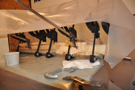
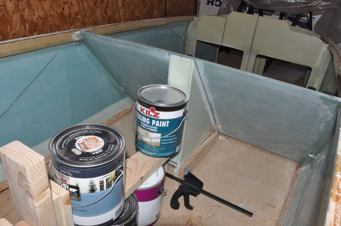
Flox was mixed up in 100 gram batches in order to avoid exotherm issues since it would take a bit of time to get the flox spread out. I used the plastic sandwich bag piping method as this allowed control over laying down the bead of flox, then it was spread out using a stir stick. Both the edges of the fuselage and the bottom were covered with flox. With Alyssa's help, we flipped the bottom up onto the fuselage and put it in place. I had drawn alingment marks on the exterior side of the foam to line up the piece. We then proceeded to find every bit of weight we could to help press the piece into place since it had bowed a bit when glassed. It took a lot of weight. If I had a kitchen sink available, I would have probably used it. Once weighed down, we scraped the excess flox away from inside and outside. Once done, we left it to cure to do the taping the next day as the fuselage could be positioned for easier taping.


After cure, all the weight was removed and the fuselage was flipped back over and placed on the table. The flox job looked pretty good. Corners were mostly rounded over with minimal excess showing up. So the task of prepping for the last step in this chapter was begun. First thing was to sand any areas that needed it. I like to roughen the flox up to ensure full adhesion as well as any area that got epoxy on it and no longer had the roughened peel ply surface. Again, my carbide grit fein tool worked wonderfully here.
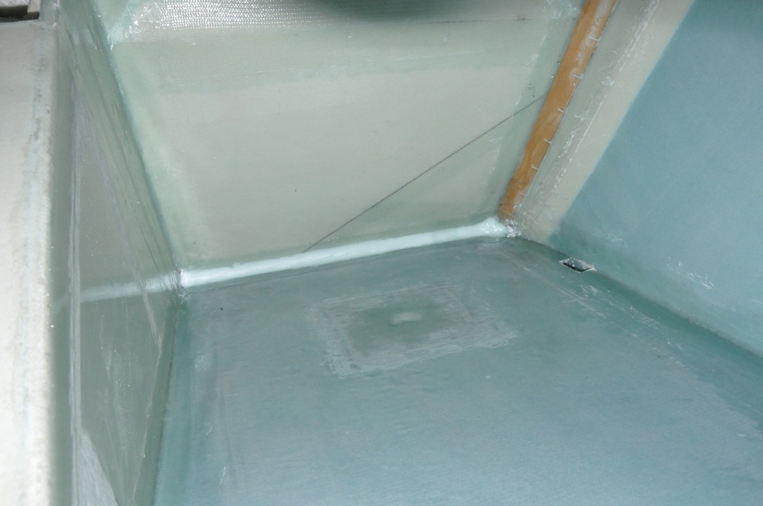
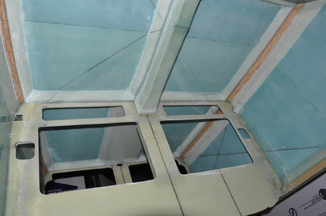
For BID taping on F22. I took from the image that only the areas where there were vertical surfaces needed to be taped which are the center and edges. The rest of run isn't tall enough to tape, but I believe it gets taped later when the nose is added. I also taped both sides of the IP (front and back) and the seatback. At first I thought you only taped the forward edge since the plans picture only shows tape on that side (and maybe it is that way), but I found references to others taping the aft area, so I decided to follow suit. In order to do so, I sanded the edges, then laid down a large bead of micro to round out the corner. The brace and the heat duct as well as the back edge of the floor against the front landing gear bulkhead get taped as well (there's a lot of taping!). All of this was done with standard 2 inch wide tape. The areas where the lower longerons are located are taped with 3 inch tape to ensure that 1 inch overlap is on the glass for the side and the bottom since you have 0.75 inches of wood to span plus the joints. I used plastic to smooth all the edges out after putting the tape in place. To facilitate taping, I flipped the fuselage onto it's side and taped the joints that were facing up. This made it easier to reach into the fuselage and helped to keep the fiberglass from wanted to fall away. After cure, the plastic was removed and any edges that didn't smooth out were trimmed to remove any sharp edges.
Before leaving this chapter, I needed to correct an issue with my seatback. In my never ending list of issues with the seatback, the top edge was only flush on one side and dipped low on the other. It wasn't as obvious until assembly that the foam was cut non-square (despite using a square). I thought I would be able to just fair it in at Chapter 8, but after further review I realized I needed to fix it. So I floxed a piece of the same foam to the surface then applied the 2 ply UNI to the front and 1 ply BID to the back, same as the rest of the seatback. I overlapped by 1 inch and peel plied. It's now flush with the upper longerons and should be the last issue I have with it (I hope). I probably should have just redone the part, but it's hard to convince yourself to cut something out and redo it sometimes. For future pieces, I'll redo mistakes like this, or better yet just not make them. With that, Chapter 6 finally comes to a close!