Chapter 9C: Landing Gear Cover And Gear Leg Fairings
For this part of the chapter (it's a long chapter, isn't it), we make a cover to go over the landing gear opening as well as add a fairing to the gear leg in order to gain a bit of efficiency. The gear leg fairings are not actually in the plans, but this is the most fitting point for them. Both of these items will be different than the plans versions.
Tips and Hints
- Do not follow the plans method of making the landing gear cover. It's apparently harder to do. Wayne Hicks came up with a great method. Follow his site (Link to Wayne's instructions) or my instructions below which are just a shameless copy of his fine work.
- When adding the strips of BID to the cover flange, try using four ply rather than two (for a total of 8 plies on the cover edge). The extra thickness is needed for proper countersinking.
- You can make your own foam covers for the gear legs, but Steve at Eureka CNC already makes some. I'm working on making a step by step install method for him to use for anyone wanting a set. We'll see how it goes.
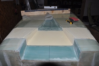
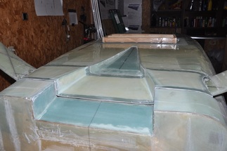
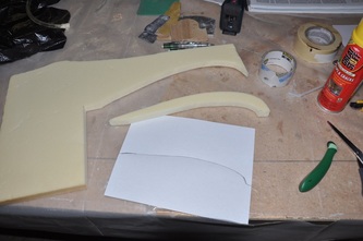
Finally, after what seemed like an eternity, I move on to a new part. At this point I go ahead and make the landing gear cover. This cover will close up the hole that the gear goes into and finish out the NACA duct as well. The plan's method of joggles and embedded metal plates has apparently caused several headaches, so I'm following Wayne Hick's method of making a cover. The firs step is to remove the landing gear strut and then fill the cavity with urethane foam (easier to carve to shape). Though larger blocks will make it easier to shape, you just need enough to get 3/4 inch thickness inside the cavity. The foam is sanded flush with the exterior surface and the sides are contoured based on the original NACA duct profile. Once shaped, you tape the perimeter of the foam with mailing tape. Place 1 inch of the tape onto the foam and the rest will go onto the exterior of the plane. This will create a release layer and retain a flat surface for the glass. Also, it would help to lay 1 inch of tape across the foam along the area where the gear legs will be.
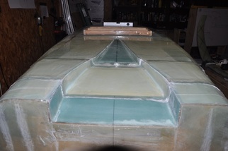
Next, the surface of the foam within the NACA duct area gets micro applied and 2 ply of BID is added at a 45 angle making sure to go past the foam some but remain on the tape. This will give you excess to trim from later. Trim the vertical edges so there isn't too much excess to pull away from the sides. Allow to cure. Trim and sand the glass attached to the NACA duct sides level with the foam surface outside of the duct, make a 1/4 inch flox fillet along the edges you trimmed, then micro and glass the foam surface on both sides of the duct. The flox will make a structural joint between the two layups.
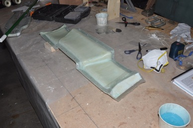
At this point the part needs to be removed for sanding and trimming. To remove it, you will need to pull out all the tape from around the edges. Just carefully pull it out parallel to the surface. Once pulled out, carefully push the piece out of the hole. You may have to cut through the edges if micro got between the foam and tape, but you should be okay. At this point, you have a rough form with the correct shape.
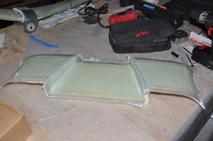
Start trimming up the piece. The gear cover should just fit into the gear area. I used a combination of my band saw and a sanding block. Next, the foam will need to be sanded away to fit. Reattach the gear legs and then carve the foam to allow the cover to fit. You will probably have to dish out the foam in the middle running parallel with the gear legs. There wasn't much foam left in a couple of places on mine. Keep going till you have the cover fitting well.
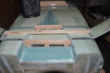
Place the cover back into the gear area and check the fit. Attach wood to make a jig that will hold the final shape that is needed to fit the area. I used tape to help pull parts that were not sitting right. The jig is attached with bondo and will be used to glass the inside surface. I made sure that the areas that were having a hard time fitting right from warping were kept in place by the jig. Once the bondo was cured, the part was removed for final glassing.
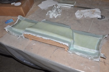
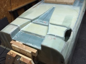
To prep for glassing, I first sanded the outer 1 inch of glass from all around the inside area to allow the new layup to bond to the original. I make sure all the foam was smoothly contoured to allow the glass to lay down, then vacuumed all the loose foam dust. The surface was covered in micro, micro fillet made in the inside corners, and two ply BID was added across the surface. While the glass was still wet, I added another 2 ply BID across the forward and aft edges. This is used to build up the thickness so that you can countersink for the screws. The edges were peel plied and left to cure. I didn't do any plastic ply on this because there were too many contours to allow it to lay well.
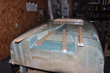
After cure, the jig was removed, residual bondo was sanded off, and the edges were trimmed. I rechecked the fit and found I needed to trim further to get it to fit properly now that the edges were thicker. I also checked the clearance with the gear legs and had to trim a bit more to make sure there was enough of a gap to avoid it hitting when the gear legs moved upon landing. My cover wasn't absolutely perfect, so there will be some filling needed to fair it in correctly. Must have changed shape despite the jig, but not enough to warrant rebuilding. Next step involves prepping for the flange layup. First, the cover is lined with tape at least 1.5 inches (2 would be better) as well as around the edge and onto the top. This protects the cover from having epoxy permanently attach it in place. The flange will be laid up directly onto this tape to conform to the cover. Next the cover is placed into the gear area. I then taped over the entire joint perimeter. This will both help hold it in place and keep epoxy from getting through the gaps. Then I bondo attached some boards to help hold it in place while the fuselage is upside down. This is ready for the layup now.
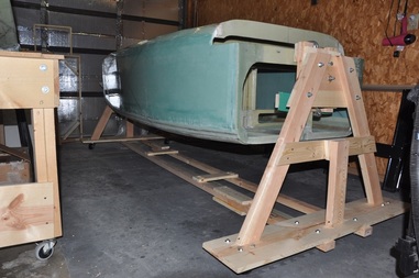
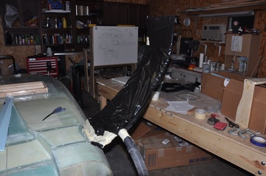
To facilitate this job and to simplify future jobs, I modifed my rotisserie to make rotating the fuselage easier. My previous rotisserie was attached to the table. The new modification now has them on their own castering stand. I can now move the fuselage around independent of the table and easily rotate it into position. This will be useful when I do Chapter 16, 17, and part of 24, which I'll be doing before I tackle Chapter 13.
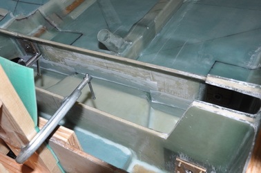
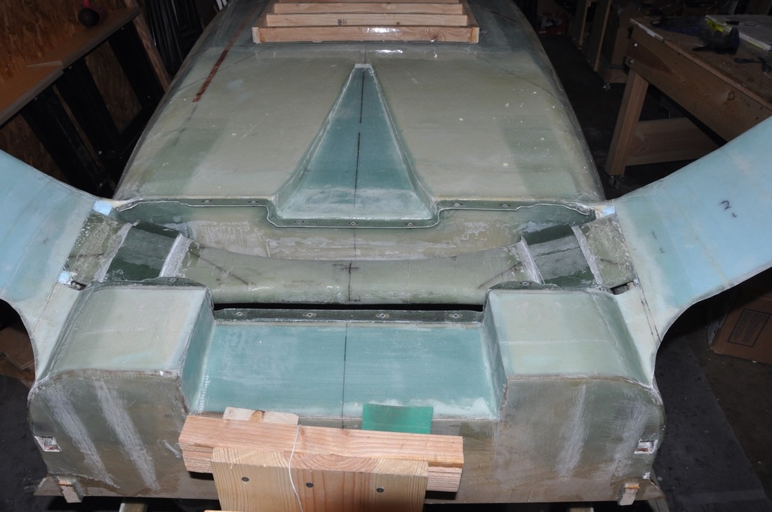
With the fuselage back on rotisserie 2.0, I was able to rotate the fuselage right side up and prepare for the flange layups. I decided to do 4-ply BID instead of 6. 4 looked like it would be plenty to allow the rivet head to be sunk into. I made up 2 inch BID tapes in long strips onto plastic, then cut out pieces that were long enough to stretch across the straight sections and 1 inch into the vertical parts of the NACA duct. I made all the overlaps take place in the vertical area since no nutplates will be placed there. It took some working to get it to lay into the corners, but I think I got it. I peel plied the edges on the bulkheads as the others are going to get trimmed. I then left it to cure.
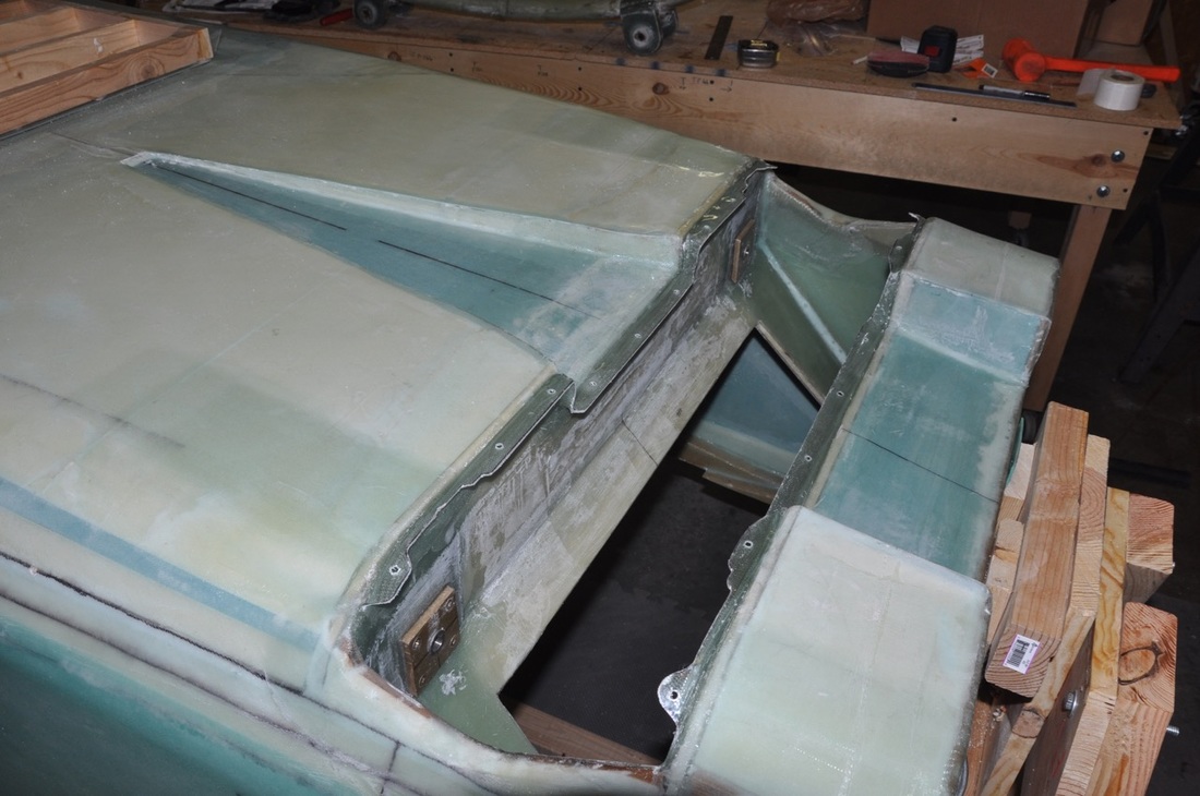
After cure, I removed the bondo attached boards. Then I laid out the screw holes and drilled through both the cover and the flange. I set the holes so they were 5/8 inch from the bulkheads since that seemed to work for Wayne Hicks. Then the cover was carefully pried up. I think this would be easier if I waxed the tape prior to the layup and plan to test that in a future attempt. At any rate, I was eventually able to get the cover off. Underneath was a pefectly fitted flange, though the vertical areas weren't as perfect as I had hoped. It doesn't matter too much as this is only to hold a cover so no big deal. All the tape and peel ply was removed.
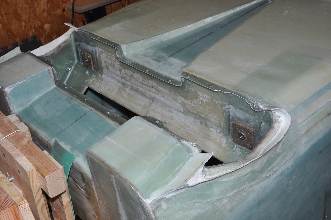
Next I went ahead and trimmed the flange so I would mutilate my hands working in that area. I trimmed enough to leave plenty of material around the screw hole, but still allow the strut to fit inside. There is extra trimming needed around the tab area though so I notched it out to allow the strut free passage through the flanges. When drilling my holes for the nutplates, I neglected to remember that I would have to notch out this area, so I had to drill new holes. Now my screws will have an uneven spacing on the ends. Just means it's functional but not perfect. Should still fly fine. The other thing I realized is that I probably cut too much clearance from the cover for the gear leg opening. This forced my last nutplates very close to the area I needed to cut out, so I would keep as much of the cover as possible to avoid this issue.
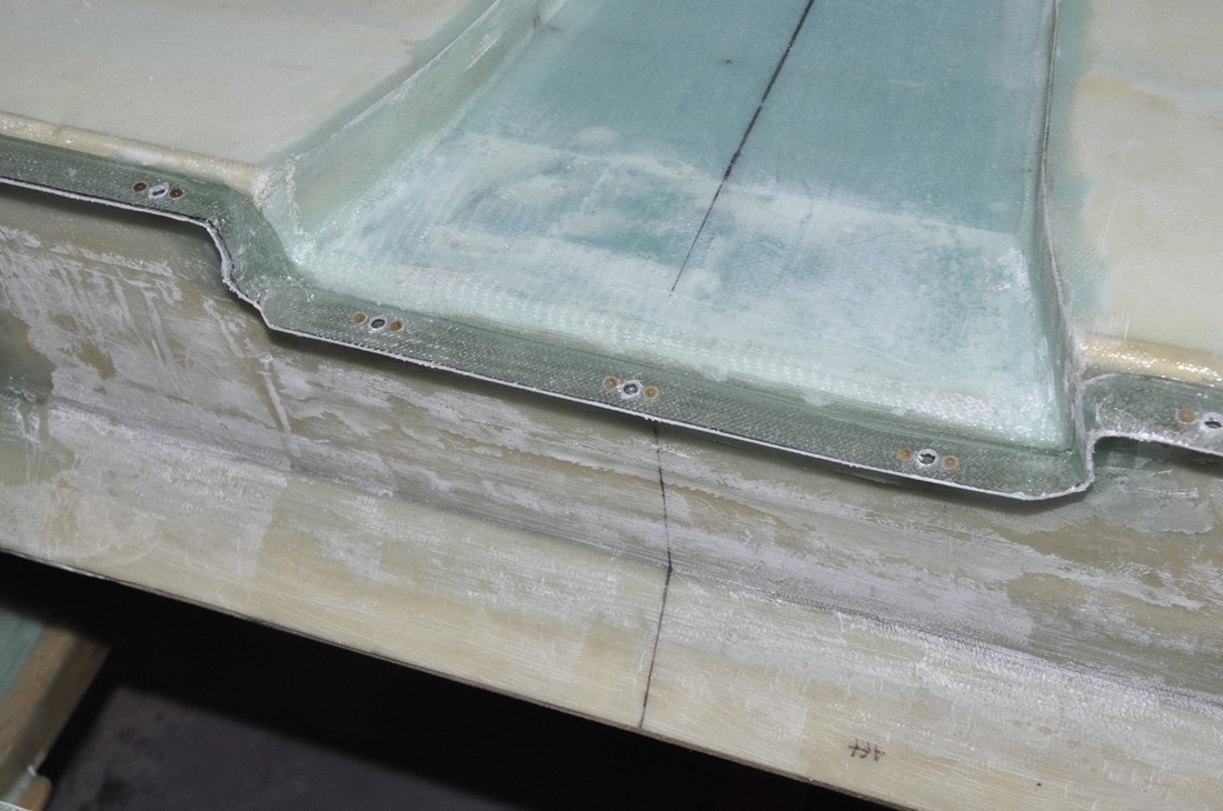
I then went to countersink the bolt holes on the cover. A fellow canard builder and flyer gave me a lesson in using a microstop. I'll eventually put in a write-up on these things. So I started in to countersink the holes for the screw head. The screws are MS24694 (10-32) screws with the corresponding K1000-3 nutplate with AN426AD-3-4 solid rivets. I quickly found out a problem: the flange wasn't thick enough for proper countersinking for the size of the head on the screw. I had six layers which I thought would be enough, but apparently it was not. However, my layups always seem to be thinner than others, so your mileage may vary. Despite this drawback, I was able to get the countersinks in, just had to be extra careful.
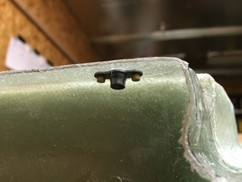
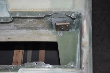
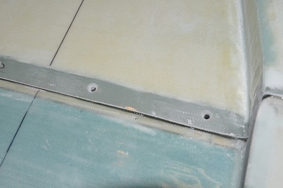
For the flange in the fuselage, I was able to properly countersink the rivets for the K1000-3 nutplate, though it was close. It's a good idea to have a couple of lengths of rivets for this as you may need longer or shorter in different areas (unless your work is much more consistent than mine). Using a rivet squeezer, I installed all the nutplates to the flange (17 total, most people use 16. For some reason I ended up with an extra one). Despite being a composite builder, my nutplate installation look okay. I won't say they are perfect, but should be enough for a cover plate. Other than filling gaps to smooth things out, this part is now done!
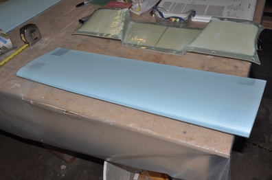
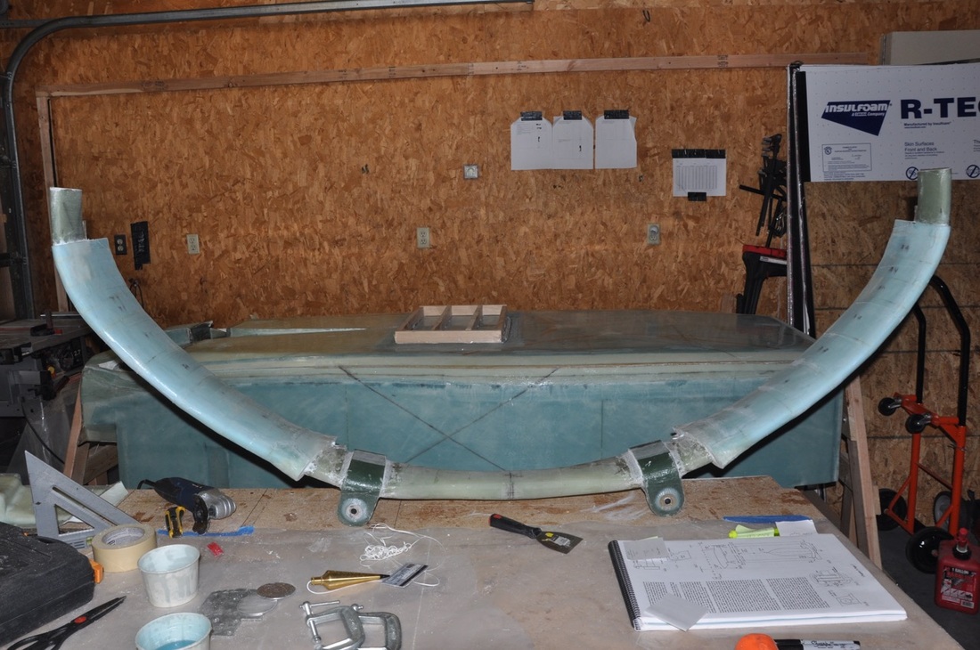
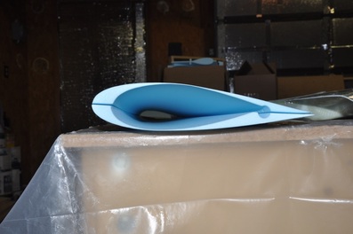
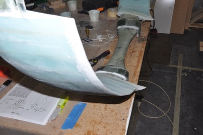
Next up is adding the gear leg fairings. This is not covered in the plans, so you have to get instructions elsewhere. I'm hoping to write up a set of instructions that will work well. Depends on how it goes. Anyway, I used the fairings from Eureka CNC that are precut from styrofoam. They are cut with a channel for running tubing down the trailing edge for brake lines. The fairing is designed to increase the chord length and change the incidence angle to align directly with airflow at cruise and reduce drag. Reports from others have shown a 3-5 knot increase from this "small" modification. The cores come cut to be as thin as possible on the width side of things to avoid increasing the thickness of the strut any. Very well done, but very fragile.
First thing is the separate the pieces and get the orientation correct. There will be two different styled halves, usually easier to tell by the placement of the conduit. One will have the conduit mostly on it's part towards the smaller area. Once you get this orientation figured out, you can carefully trial fit at the ends of your strut to see how they match up. The halves will not bend onto the strut without breaking, so don't try to do that. What you want to make sure is that the trailing edge is aligned with the leading edge parallel to the centerline of the fuselage. One direction will do this, the other won't. Hint, the conduit will be on the outside half of the fairing towards the strut end.
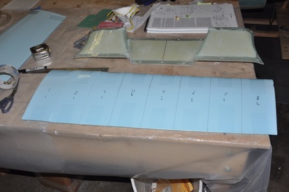
Next thing is to cut the fairing into pieces that will fit on the strut better. Here's what I did:
- Set the halves together. Lay a piece of tape across both leading edges at the ends to connect both halves.
- Draw lines across the piece at 4 inch intervals for the first 20 inches. This will be the cut lines to give a total of five 4-inch thick parts.
- After the fifth part line, draw lines at 2 inch intervals. This will coincide with the greater curved section and the smaller pieces will fit better. I did a total of 4 pieces (8 inches in length).
- Number each piece so you know which piece it is and which side it goes to.
- Cut the pieces out. I used a band saw, but a razor blade or hot wire would work fine.
- Tape the trailing edges and leading edges of each piece to hold them as one unit, then slip onto the strut to check the fit. There will be gaps between the pieces that will get filled later.
- Starting at the fuselage side of the fairing, cut three pieces to 4 inches long.
- The next set of pieces cut three to 3 inches long.
- The next set of pieces, cut three pieces to 2 inches long.
- You should have 27 inches in length which I found to be about right.
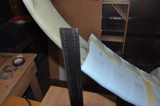
Next you need to set up the alignment. There appear to be several ways to do this. I tried making alignment lines on the fuselage and floor as others instructed, but I just couldn't get this to work very well without being cumbersome. The main thing is that the trailing edge should be level with the leading edge on lines parallel to the fuselage. With the fuselage upside down and set so the nose was at a 2 degree angle to mimic cruise (in this case, it's 2 degrees down towards the floor since it's upside down), I then made a flat base under the strut and used a tall square to measure the height of the LE and the TE at the same buttline. They should match. For me, the fairing did a good job of pre-aligning to the correct spots. I made reference marks along the strut and the foam pieces to match to later on. Then I removed the fairings.
Here's where things didn't quite go as I had hoped. The directions I got from others that installed them have you do the following:
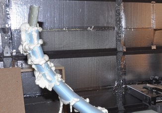
- Micro the interior of the foam fairings.
- Install onto the strut. Use tape to hold the piece together and as tight as possible onto the strut.
- Once all pieces were in place, wrap in plastic and pull a vacuum to suck down onto the strut and hold for cure.
If I was going to redo this over again (and I'm not), I would use Great Stuff foam to install. The reasons are that it gets very sticky and will start holding sooner, it's quicker to apply, and it will be a similar consistency to the styrofoam making sanding easier. Here is what I would do next time:
- Sand the strut surface to help with bonding.
- Tape over the leading edge of each fairing half to form a hinge. Sand the conduit opening to fit the tubing without distortion.
- Spray the interior of the fairing with enough Great Stuff foam (standard type is fine) that you can spread it onto the entire surface.
- Spread the foam with a stir stick and allow it to expand and get sticky, but not cure. The more you let it expand, the less expansion you will get later.
- Press one side the fairing into place on the strut, add your conduit tubing, then fill the space around the tubing if needed with more Great Stuff and attach the other half of the fairing. Tape the trailing edges together to hold in place. Press out as much excess foam and remove the excess.
- Take a long piece of tape and starting from the leading edge place the middle of the strip on the leading edge and pull both sides of the tape as tight as possible towards the leading edge. You're trying to compress the pieces against the strut. Again, remove any excess foam that squeezes out.
- Continue on till all pieces have been done.
- The foam will probably continue to expand a little, so the fairings will have to be pressed into place periodically to squeeze out the excess. At some point, the foam will stop expanding and start gripping.
- You can try using a plastic bag and vacuum down the pieces if you know what you're doing (I apparently don't).
- After cure, trim off any excess foam and recheck alignment.
Well, since I didn't do that (and it's untested so for all I know it may be worse), I have to go back and fill all the voids with Great Stuff or micro and re-contour. The two main things I'll be fixing are the width of the thickness (filling the voids then sanding down to near the thickness of the strut), correcting the trailing edge direction, and repairing the broken pieces. Sigh, more time spent that I had hoped to avoid. More of that FAA learning experience.
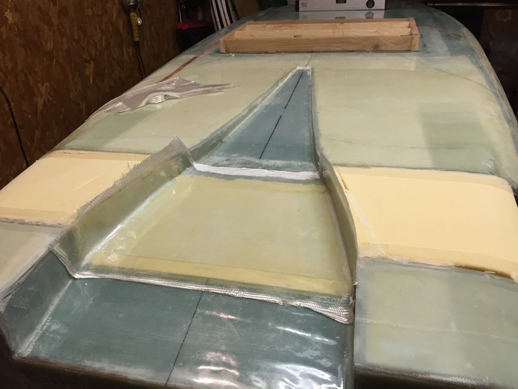
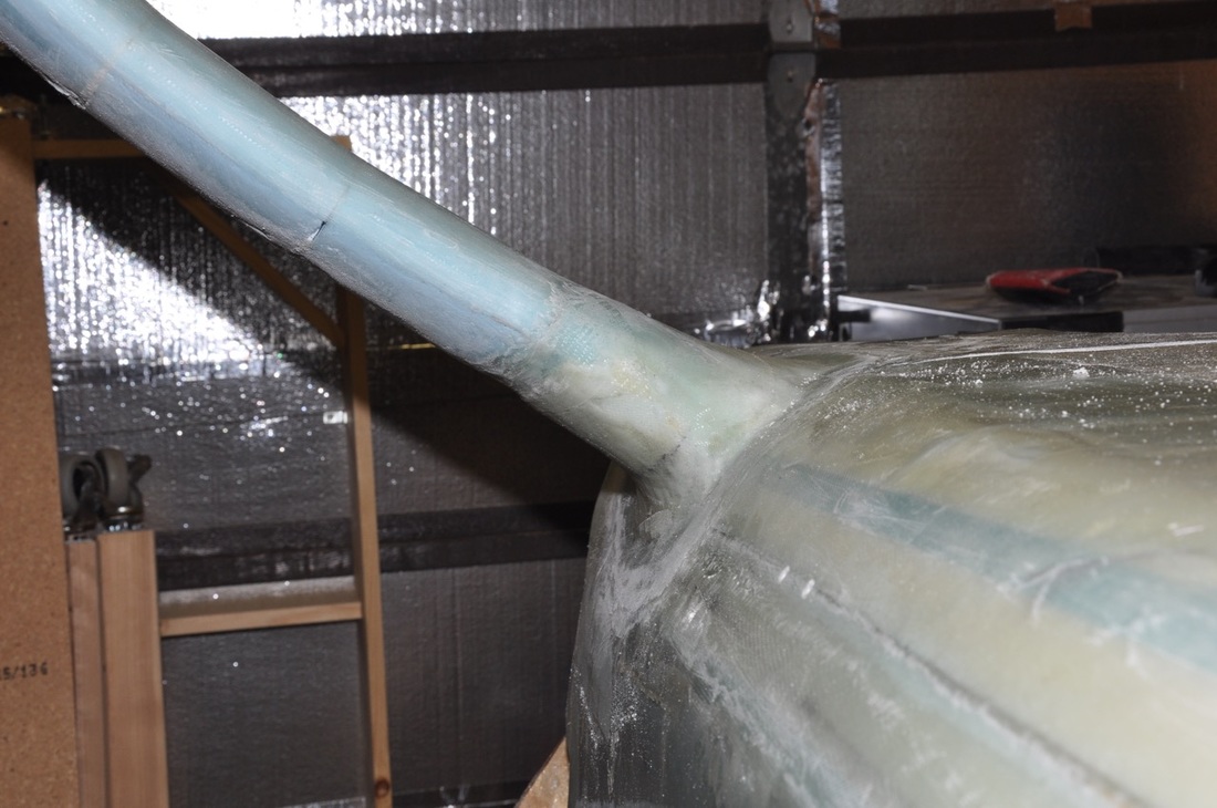
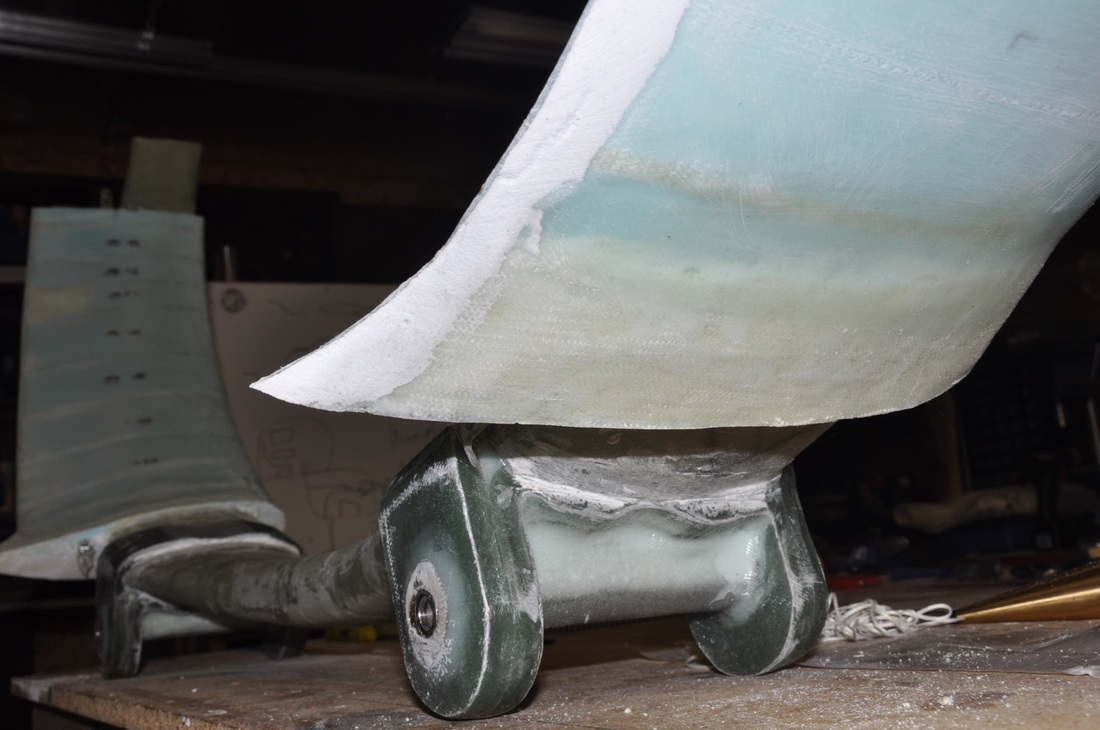
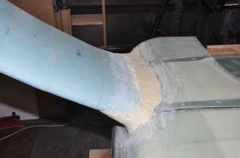
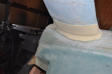
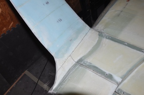
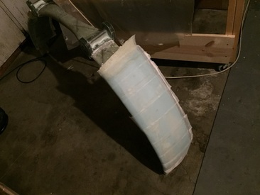
After a lot of work, I finally got it done. It's far from perfect, but I'm just done at this point and I'm not going to spend more time with it (not the best attitude, but I've been on this chapter long enough). I added tape to the gear leg cover on the inside edges where it comes in contact with the fuselage. This will avoid sticking from epoxy drips later. At this point, you would normally glass over with 2-ply BID or 2-PLY Uni at alternate 30 degree angles. However, I decided to go ahead and build up my intersection fairing, then glass both at one time. This should save some work later and make it more uniform. For these I just followed Wayne Hick's method for making a splitter, but I just built up the foam around the area with pieces of urethane using some Great Stuff to make it stick. The splitter works by adding enough thickness above the strut to allow for movement as the strut is loaded by weight. A part is made perpendicular to the strut and in the direction of the movement. The rest is just faired in to avoid making more surface area than necessary. I cut the urethane foam similar to what Wayne shows on his site thought I made the piece 1/2 inch just to ensure enough clearance is provided. The edges were rounded over using a round piece of wooden dowel and sand paper. I didn't have enough urethane foam to make full fairing cutouts as Wayne did, so I just made the upper section half then used scrap pieces to cover the lower section. If you have enough foam, just do the entire piece. Make sure that the fairing is large enough to cover the opening between the strut and the fuselage.
Next the foam was sanded to try to smooth out the fairing contour. The glassing will be done in two rounds similar to how the wings are done. For glassing, I microd the styrofoam surface and filled all gaps as best as I could. I tried to smooth out some of the transitions between pieces, but this was easier said than done. I used a more liquid micro doing the urethane since it's so fragile. I then took two lengths of BID that were wide enough to go from the edge of the fairing to wrap around the leading edge of the strut. This was long enough to also cover the entire strut, intersection fairing, and 1 inch onto the fuselage surface and gear leg cover. Wrap the entire surface in peel ply ensuring that the edge of the glass are well covered to make a smooth transition. Allow to cure.
After cure, I removed the peel ply, trimmed the excess glass, and checked the layup. Everything looked good enough, so I started prepping for the second layup. Ultimately, I plan to glass the other side of the strut with the strut off the fuselage and turned so I can glass that side facing up. However, it'll work best if I go ahead and glass over the intersection fairing first. I sanded 1 inch onto the fuselage and on the glass on the fairing leading edge, then microd the foam and glassed 2 ply BID making sure the cover the entire intersection fairing, 1 inch onto the fuselage, and partly onto the gear leg fairing. This was peel plied and left to cure.
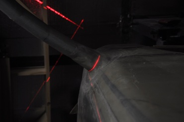
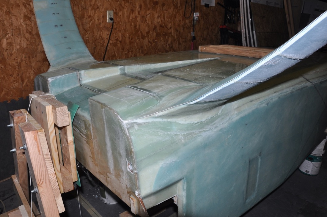
After cure the peel ply was removed. Now is the time to lay out the cut lines. For the splitter to work correctly, the cut must be the same distance out from the intersection as the height of the fairing on the top surface. I decided to make a 1/2 inch high fairing, so I measure out 1/2 inch. The other important thing is to make the cut in a direction that is perpendicular to the gear leg surface. Since the foam I used to make the fairing was 1/2 inch thick, I just set the edge of the foam as the cut line. Then I used a laser line to match up the line and draw out the cut line on top. This works very well when you have a curved surface.
After drawing in the cut line, I also drew in the cut lines for the cover by following the original cover lines and extending them to the leg cut line. This will free up the cover and allow the gear leg to move out. Once the lines were drawn, I carefully trimmed along my lines with the fein making sure I only cut the outer glass and not the strut underneath.
Update: I miscalculated when making my cut lines. I was continuing the curves of cover without thinking about the clearance of the strut. I can still get the strut out, but it does require some maneuvering. I would suggest keeping the lines straight to the fairing cutline.
Update: I miscalculated when making my cut lines. I was continuing the curves of cover without thinking about the clearance of the strut. I can still get the strut out, but it does require some maneuvering. I would suggest keeping the lines straight to the fairing cutline.
After cutting the glass, I ran a razor blade along the cut to cut through the foam. Then I spent time carefully prying up the cover. I was able to get the cover up with most of the foam attached to the cover. Any foam left on the strut where the cover was I scraped away. For the foam left on the cover, I sanded it smooth within the contours of the glass and added 1 ply BID over it to encapsulate the foam. For the foam left on the fuselage fairing, I removed the foam away from where the strut will need to move around. The remaining foam was covered with micro to encapsulate it.
After removing the strut, I flipped it over to put the unglassed side upright. I trimmed the foam on the trailing edge to make a nice transition for the glass to glass bond, then sanded the foam to contour. Also sanded down the glass 1 inch for overlapping the layup onto. I applied micro, glassed 2-ply BID, peel plied, and allowed to cure. After cure, the excess was trimmed away. At this point, the only exposed foam was at the two ends of the fairing. I decided to just cover these with micro to encapsulate them.
The last thing I needed to do was add the micro fill to the trailing edge. I mixed up fairly dry micro, then tried to over-apply it to the depression along the trailing edge. After cure, I sanded it to contour using 36 grit sand paper. I missed a few spots, but these will get filled when I do the full contouring down the road. For now, it's mostly in shape. This was the last thing I needed to do and can now move onto the axle installation.