Chapter 11: Elevator
Well, we made a wing, now it's time to add some moving surfaces to it. This chapter covers the making of the elevators that will then get attached to the canard. This will be using the first set of metal control rods that we have come across. As I'm not a metal worker, I bought all my parts from the Cozy Girrrls. As always, the parts are great and well made.
Special Tools Needed
- Drill guide for tubing (ACS #12-02937 or equivalent).
- #12 reamer
- 1/4 hex wrench
Tips And Hints
- The NC-2 orientation isn't so obvious. Chapter 11 Page 1 Figure 4 shows the location of the hinge pin hole and the orientation of the slotted area on NC-2 with relation to the elevator. As long as you lay out the torque tubes in the orientation of the canard foam points and the tubes should be mirror images of each other with reference to the pockets, then install each NC-2 all the same direction it'll be fine. The tubes can be swapped to get the correct orientation.
- The Eureka CNC elevators are cut the full length rather than in two pieces, so they do not need to be glued together. They can also be cut to the final contour so they don't have to be sanded.
- Cozy Girrls make all the specialty parts very well. The hinge pin already has the tapered end to facilitate installation. Well recommended.
- When getting ready to drill the holes and install the pop rivet for the NC-2 inserts, install the hinge pin first to help hold things in alignment. This will facilitate installation later on.
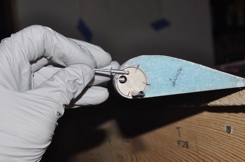
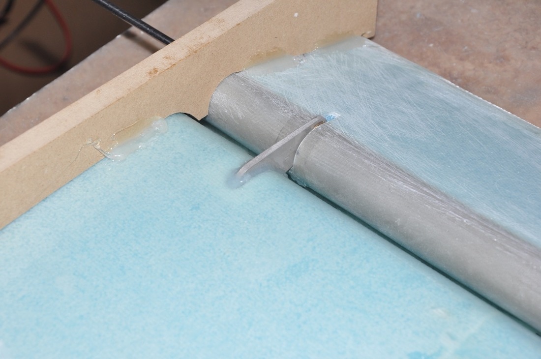
- To ensure that the drill is centered on the tubing before drilling, place a razor blade or other thin flat piece of metal. Press the drill down onto the surface with the drill off. If it's centered the metal will be level. If it's off center, the metal will tilt. Move till the metal is flat with the drill pressed down.
- Hold off on filling the holes on NC-2 with grease. The area can be protected by tape or clark foam rather than grease which could make a mess and interfere with bonding later.
- Purchase or make four NC-7 jigs. This will allow you to glue both foam cores to the tubes at one time instead of waiting for one to cure.
- Add AN960-10L washers to your parts order. You will want 2 per bolt when attaching the AN3 bolts to the torque tubes to both give a bearing surface and to keep the nut from bottoming out.
- When installing the BSPQ-44 rivet into NC-6, the rivet will be too long to fit all the way. To make it fit, push the rivet into the hole as you squeeze the puller in order to get it to fit correctly. The rivet will shrink as it pulls.
- When drilling the holes for the AN3 bolts, use a smaller drill size and ream to the correct size with a #12 reamer in order to make a tight fitting hole.
- Make a reference mark on the elevator inboard side on the bottom that shows the location of the hinge pin. Make a mark on the outer portion of the spool that fits against the elevator for the hinge pin location. This will make lining them up later much easier. Don't worry about matching the angle shown in the plans. It's better to have the hinge holes aligned.
- Make sure that you leave plenty of room on the ends of the elevators when the torque tube is assembled and during the rest of the construction in this chapter. The hinge pins need room to be pulled out several times.
- Add 1 ply BID to the sides of the outboard weights to add some shear resistance.
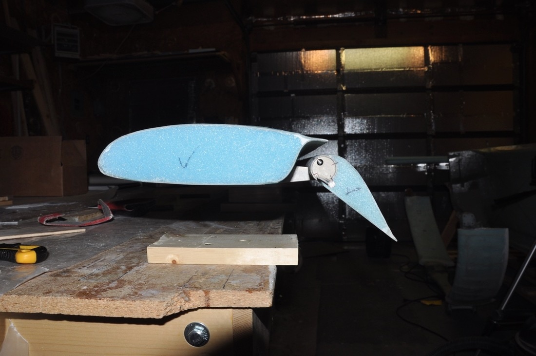
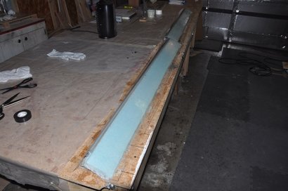
First thing I did was to get out the elevators and verify that they matched the contour of the original plans. As expected, they were perfect. I got the final contoured version so I had to check the final shape, not the hotwire cut shape. These have some thin edges on them, so you have to be careful handling them.
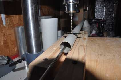
Next I got out my Cozy Girrrls parts for the torque tubes. The tubes already have the windows cut and the parts are alodined. NC-2 inserts are already cut properly. I checked the fit and they were perfect (as expected from them). The window alignment was confirmed with the foam inserts in the canard. Then the inserts were installed and the hinge pin was pushed through both. This will help hold them in place while the hole is drilled for the pop rivet. A #30 hole is drilled as centered as possible through the tube and the NC-2 insert where the larger hole is located. I used a trick that Bernard Siu showed where he used a razor blade to check that the drill was centered on the tube (See Tips above). The holes were drilled, then the hinge pin and inserts were removed so that the hole could be deburred. I had to use a countersink bit to debur the holes. Once deburred, the inserts were reinstalled, the hinge pin put in place, then each part was installed with the specified pop rivet ensuring full compression of the rivet. All the joints between NC-2 and the torque tube were sealed with gel super glue to ensure no epoxy leaked in during the layups later.
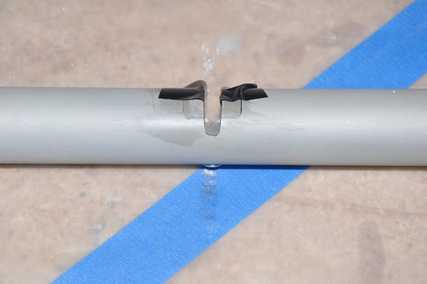
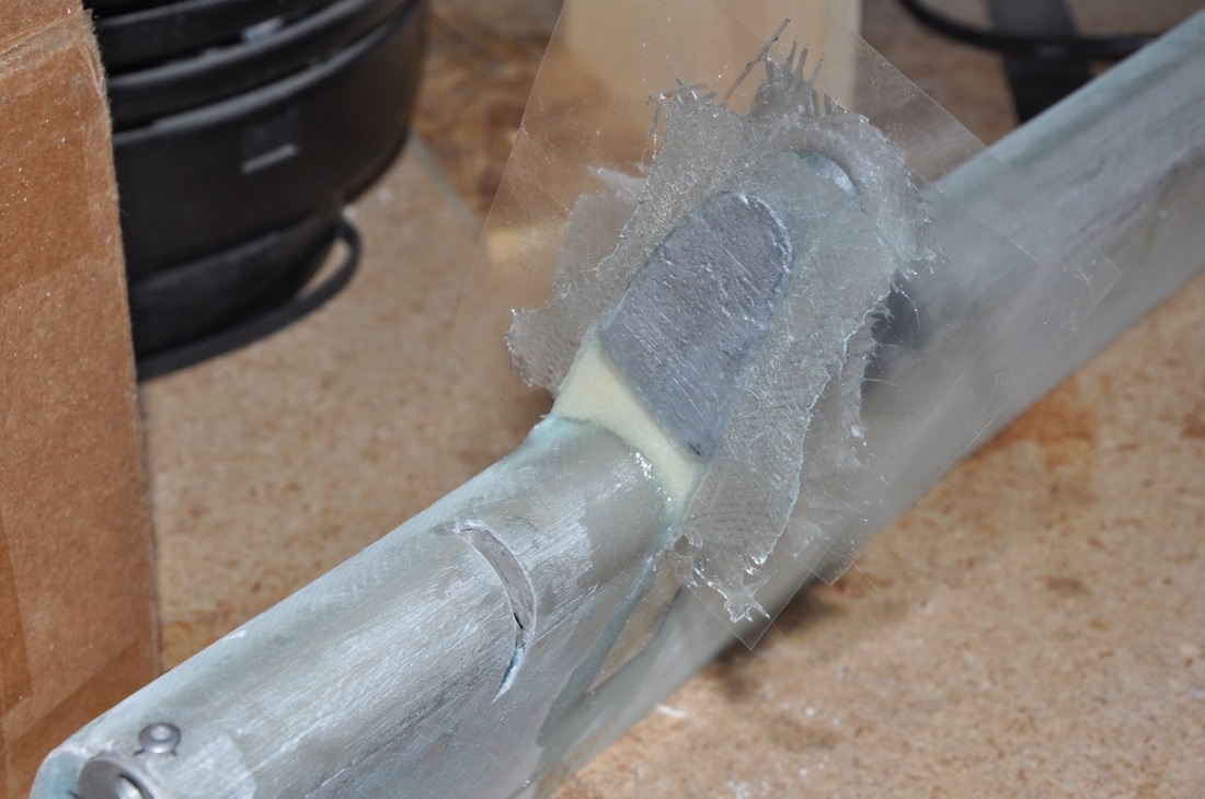
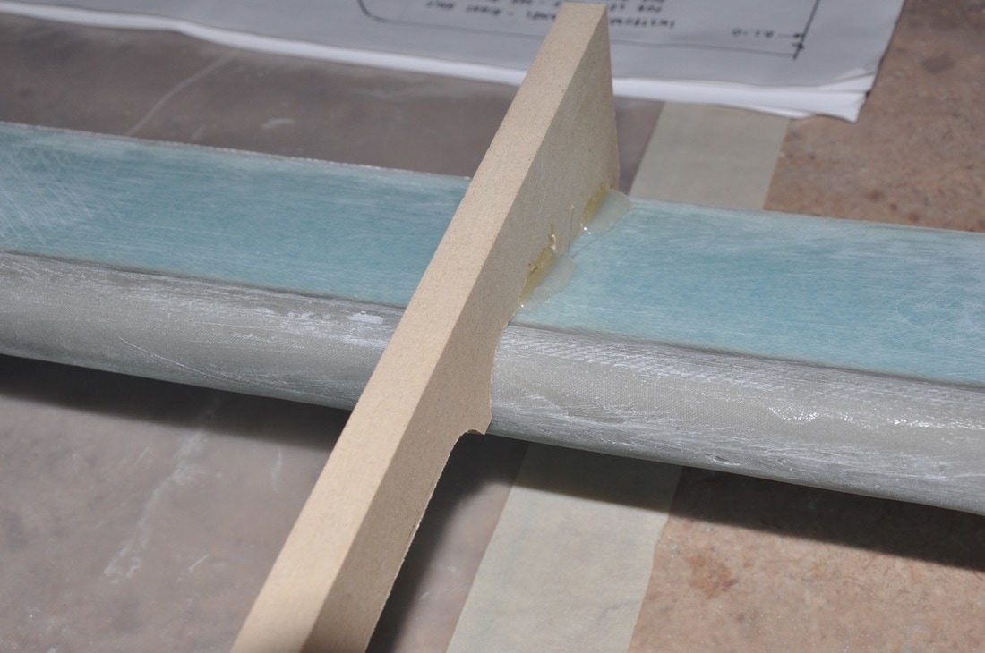
The next step involves filing notches in the torque tube to match the slot in NC-2. The directions make it sound like you only notch one side, but don't really explain which side. I found reference on the Cozy forum that it's best to notch both sides. To do so, I first protected the sides of NC-2 with electrical tape to avoid scratching it. I then used a flat file to make the main cut in the tubing, then using a combination of round and flat needle files to open the sides flush with NC-2 and round the two bottom corners. You don't want to make the corners square or you could have a stress point. The round file helped to round out the corners to avoid this. It took some time, but eventually I had all four done. While they don't look as nice as the original Cozy Girrrls' cuts, they should be good enough and won't be easy to see when installed anyway. The last thing to do is to use super glue to seal the joints where NC-2 contacts the tube. This ensures epoxy doens't get inside and mess up the hinge pin install. I didn't fill the holes with vasoline as I'll wait till I need to do something and will probably use tape rather than grease to protect them.
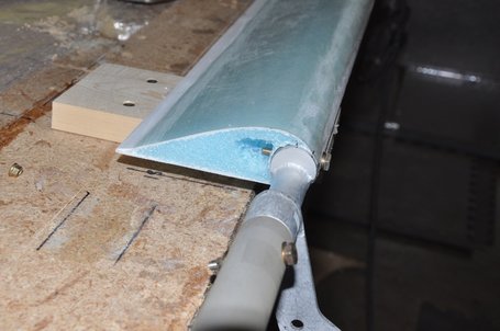
Next step was to glue the foam to the tube. NC-7 is a jig piece that allows the proper positioning of the elevators on the torque tubes. The fit of the NC-7 on the hinge pin should be snug, but still allow movement of the hinge pin to install it through all parts. After ensuring the proper orientation of the inserts, the hinge pin was installed with the jigs in place, the inside curved surface of the elevator core was coated with micro, then the foam was slipped over the tube ensuring the outboard end (the one with the insert closest to the tube end) was flush with the torque tube. I didn't have a problem slipping the foam over the tube with the micro added. I then weighed down the elevator on a flat surface and allowed to cure after checking the alignment. The same was repeated for the other side but making sure it was a mirror image of the other.
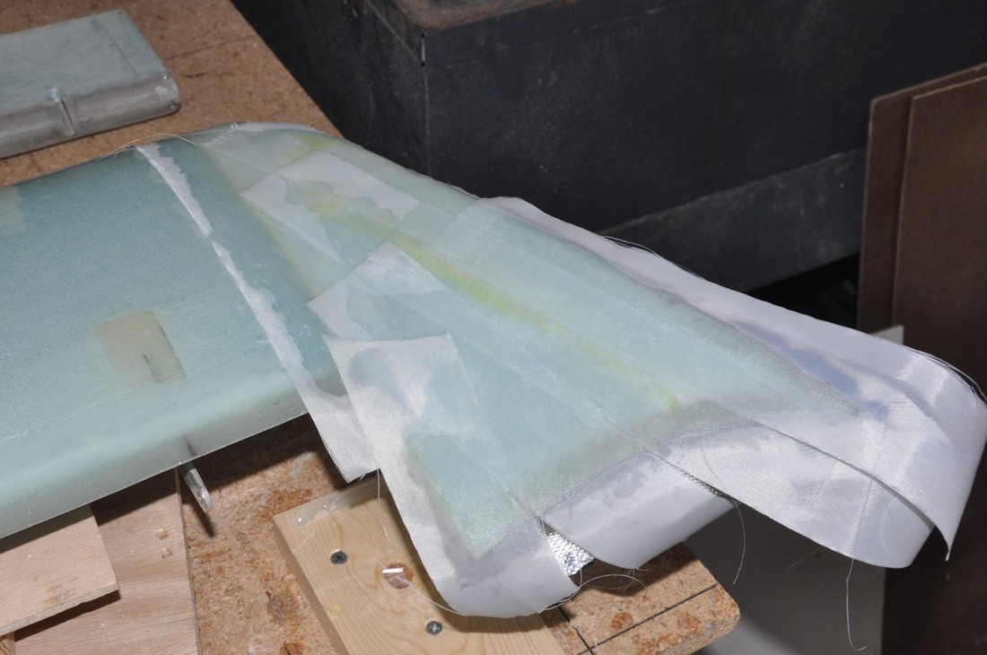
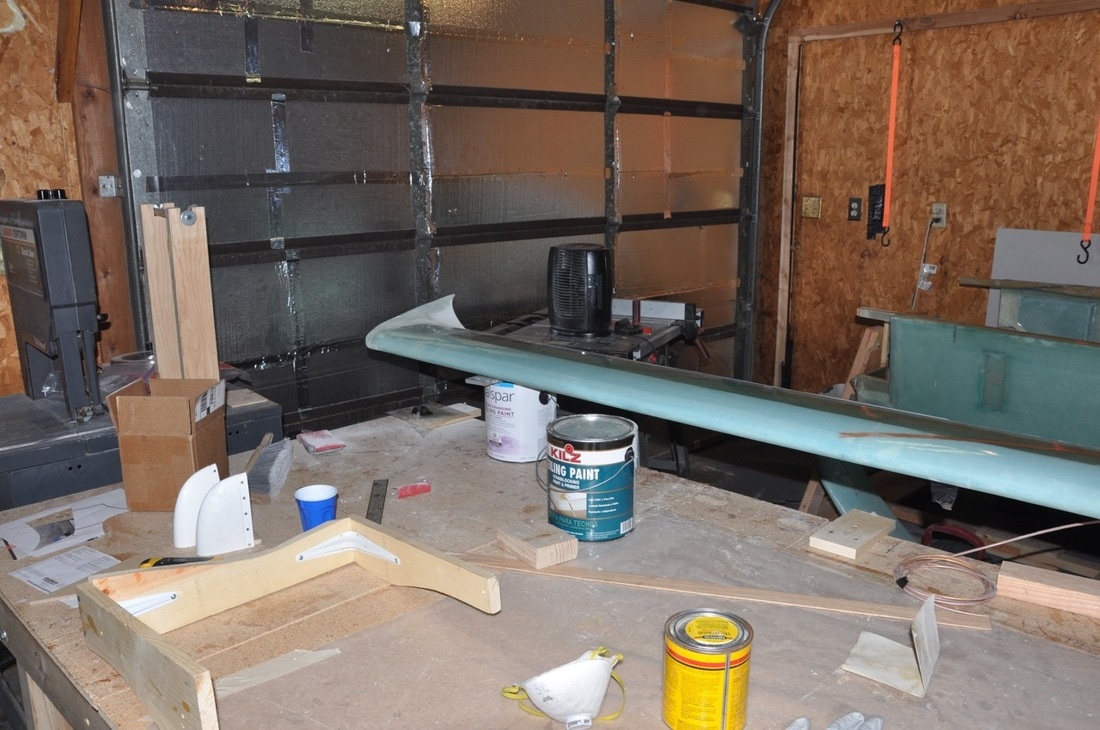
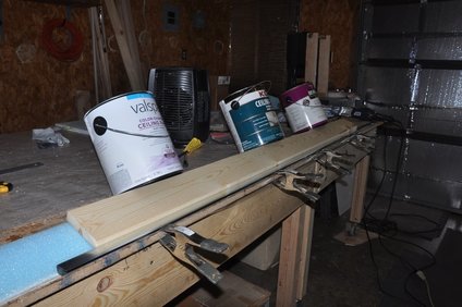
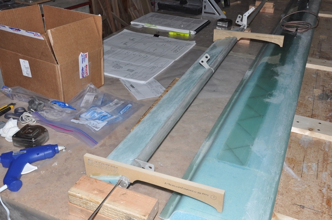
Next step was to jig the elevators to the table with the bottom side up. I first made sure the table was nice and level. Next I placed a strip of mailing tape on the table to keep the glass from sticking. I was going to jig the cores down using the outside cuts of foam that the cores came from, but apparently I damaged them getting the cores out, so I couldn't use them. I decided to just 5 minute epoxy them down to the table. As long as I don't press hard on the foam, they should remain straight. I made sure that the trailing edge was on the tape to avoid sticking to the table. The layup consists of 2 ply UNI cut at 30 degrees. I used a protractor and a laser line to establish the 30 degree angle lines and layed a piece of tape on the table to act as my cutting reference. Worked very well. I went ahead and cut the plies for both the bottom and top skin since I was at it. I also taped the edges of the cut and cut through the tape to help hold everything in place (similar to what we did with the canard plies). Last thing was to tape over the hinge pin holes in the NC-2 inserts to avoid epoxy getting in.
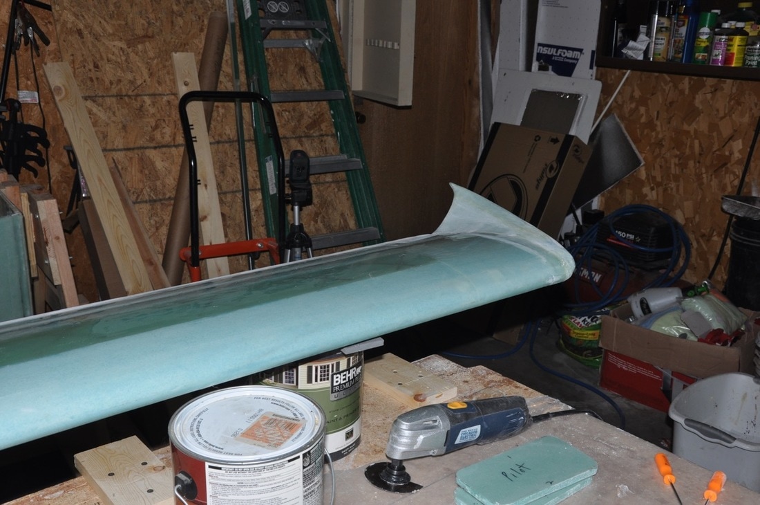
The layup was fairly straight forward. To minimize the weight gain across the foam, I mixed the micro on the dry side. The hope was to make balancing easier down the road, though it is a bit harder to spread out. I scraped off as much excess micro as I could and I let it tack up some so it wouldn't try to absorb more epoxy later. The first ply of UNI was laid out and the angle of the fibers checked. I then trimmed the excess glass allowing for the overlap onto the torque tube as stated in the plans. After wetting out, I removed as much epoxy as I could without making dry spots (again, trying to keep weight down). The second layer went on after that but with the fibers oriented in the opposite direction. This gives you a V-pattern with the two plies providing the stiffness in both directions. I went ahead and peel plied the leading edge area to smooth out the cut edge as best as possible (hard to get peel ply to stay on such a tight radius) and then I plastic plied the rest of the surface. Even after getting as much epoxy out before the plastic, once the plastic was on it's amazing how much more comes out. I checked at low angles to make sure the parts were still flat and straight. Left this to cure overnight.
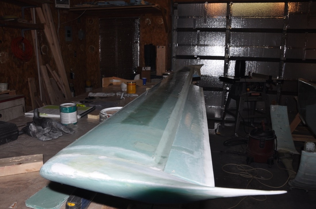
After cure, the plastic and peel ply was removed and the excess glass was trimmed. Using the contour checker the end of the trailing edge was marked and cut. I checked for the table to be level, then I turned the elevators over and mixed up bondo to attach them to the table. I used a long flat metal piece to clamp the trailing edge down and weights to hold down the leading edge. After the bondo cured, I cut the 0.3 inch away from foam on the trailing edge to make the glass to glass bond. I rounded the foam to allow the glass to lie down easily. I sanded the leading edge where the glass layers were to make a smooth transition and take care of any loose fibers. I placed mailing tape on the table under the leading edge and along the trailing edge to avoid gluing things to the table by dripping epoxy. When done, I microed the surface with fairly dry micro and glassed just like the bottom layer. After the glass was down, I placed dry micro along the trailing edge, then applied a strip of peel ply and squeegeed to match the contour as well as possible. Then I peel plied the leading edge and plastic plied the rest of the surface, squeegeed everything well, checked the contour, then left to cure.
After cure, I removed the peel ply and plastic. Using the contour template, I marked the trailing edge to trim to length. When I made the initial cut, I cut away from the edge then sanded to shape. This helped because some of the micro would chip out when cutting. It also allowed me to get the edge as straight as possible, though slightly over sanded in a couple of spots that I'll have to fix later on. After trimming all the glass, I used various tools to open up the NC-2 slots in the leading edge. After I finished, I trimmed off the excess elevator to make it flush with the torque tube (directions mention to do this later but there was not reason to wait) and weighed the two elevators. Left was 798 grams and the right was 793 grams. 5 gram difference was pretty good. I don't know how they compare in weight to others, but that seemed pretty good. This weight includes the torque tube with NC-2 inserts but before NC-6 ends were added.
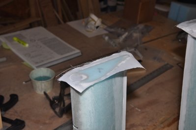
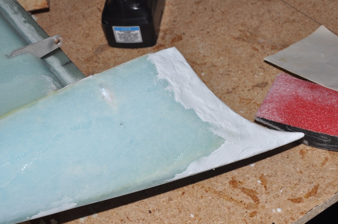
Next up was to glass 1-ply BID to the outboard end of the elevators. First you have to make a small flox corner for strength, then micro the surface and apply the 1-ply BID. I used a utility knife to remove foam at an angle to make a triangle profile for the flox. Then a piece of BID was cut to match the profile as well as possible and applied and covered with peel ply. After cure, this was trimmed.
Next up was installing the NC-6 inserts into the outboard ends. First, I removed the set screw that was already installed in the Cozy Girrrls part and placed it in a bag to save for later. Next, I made a mark to index the hole for the setscrew. Then I measured the distance to the center of the hole along the edge face. These two things will help to locate the hold after install. Next, the part was installed in the end using the hinge pin to align it with the others. Next, a #30 hole was drilled aligned with the larger hole in the part. A BSPQ-44 rivet is used to install. This one was a bit tricky as the rivet doesn't fit all the way into the hole. In order to use it, you push it into the hole as you squeeze the rivet puller. If done correctly, the rivet head will be flush when you're done. I'm not sure why you can use a BSPQ-43 as it looked like it would be long enough, but I don't know enough about rivets to know what the minimum length needs to be, so I just used what was called for. It wasn't bad to do anyway. Then using my alignment markings, I drilled out the hole for the set screw carefully to avoid drilling out the threading. The hole will not allow the set screw in, so I ran a 10-32 tap through to tap the tubing. The set screw inserts with no problem.
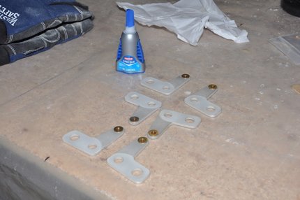
In preparation for installing the hinges, I decided to make my life easier and lightly attach the washers to the NC-3 hinges. To do this, I just used a VERY small dab of super glue away from the hole and placed the washer over the hole and aligning them up. After the glue cured, I flipped it over and did it on the other side. Now the hinges will go in without having to mess with the washers.
UPDATE!!
This failed miserably for me. It did work to make the insertion easier, however, when the washer popped off there was drag in the hinge movement from the glue rubbing. It happened on one, so knowing the failure mechanism I took the rest off and carefully scraped the glue away. I'ts not too bad to position the washers and the hinge anyway. Seemed like a good idea.

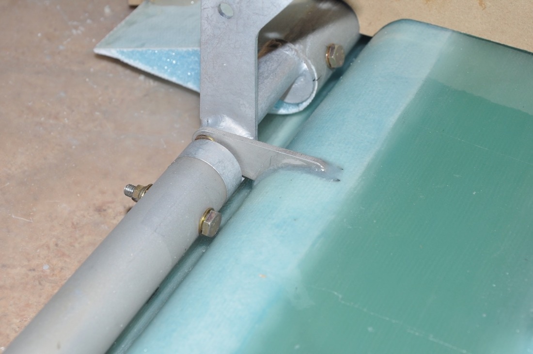
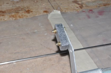
To assemble the rest of the torque tube, you get a 30.2 piece of aluminum (which was provided in my parts from the Cozy Girrls) and your two CZNC-12A pieces: one left side and one right side spool. These attach to the tubing with the NC-2 like insert area on the tubing side. With the fit checked, I installed the hinge pin and placed the pieces as shown in the plans (balance arms facing up) on a leveled table, then clamped a board across the two arms to hold everything level. The hinge pin will be a very tight fit through the spool pieces, so I helped myself by polishing the surface with fine steel wool (there was some roughness on them) and polished the metal to make it slip as easily as possible. Once installed, I could drill the holes for the AN3 bolts. Here's the order I did for drilling these holes to get a tight fit:
Helpful Hint!
Before you assemble these parts, make a mark to show the location of the hinge pin hole on the spool pieces so that once assembled you know where the hole is. It'll help in the next steps.
- Mark the locations on the tubing, then use a punch to make an alignment dimple.
- Drill with a small drill bit (#30 or similar).
- Drill with a #13 or a 3/16 inch drill bit.
- Ream with a #12 reamer.
Helpful Hint!
Before you assemble these parts, make a mark to show the location of the hinge pin hole on the spool pieces so that once assembled you know where the hole is. It'll help in the next steps.
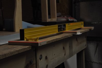
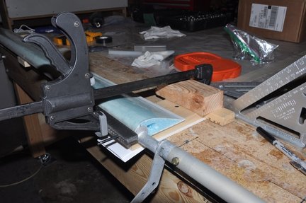
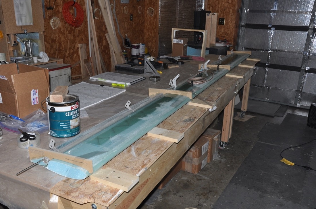
Next up was to set up the table to allow the installation of the elevators to the middle torque tube. First, I cut 6 pieces of 1x4 to 7 inches. This is two more boards than the plans call for as I wanted to support the middle of each elevator. It may not be necessary though. I then positioned these boards on the table so there was 1 inch overhanging the table. I used a laser line to establish a reference line for each board to be positioned as straight as possible. I then used the self-leveling laser line to check that they were all flat and at the same height. I adjusted a few with washers under the boards. I also checked the front to back level of each board and make them all the same as much as possible. Once I had this, I screwed them down to the table (easier to remove than bondo). I then took the time to line up the elevators and the torque tube, then I held it in place with hot glue. I used hot glue rather than bondo because it's easier to remove. However, it might have been better to use bondo anyway.
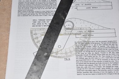
This next step took a bit to figure out. You are suppose to insert the hinge pins to align all the parts together. First, I neglected to put them in before jigging the elevators. One side was only a couple of feet from the garage door, so I had to open the door with 19F temps outside and let my precious heat out for a moment to install this hinge pin. After that I found that even with the hinge pin in, the middle torque tube can move quite a bit. Trying to find the aligned position was tricky because I couldn't follow the hinge line with the 1x4 boards in the way. So, I decided to measure the angle of the counter weight arm against the flat bottom of the elevator. I used the M drawing and the one in the plans to see if they matched. The angle was 112 degrees for my drawing using the front facing edge of the counter weight arm. This was my reference number.
Helpful Hint!
Forget the drawings in the plans. What is really important is to align the hinge pin holes. If you marked the location earlier, then it should be easy to line up the hinge pin holes for assembly.
Helpful Hint!
Forget the drawings in the plans. What is really important is to align the hinge pin holes. If you marked the location earlier, then it should be easy to line up the hinge pin holes for assembly.
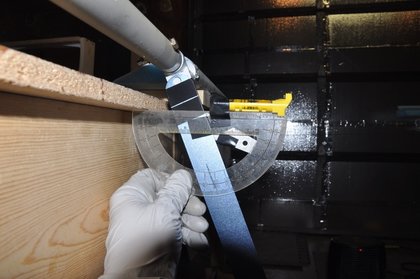
Next up, to extrapolate this angle, I taped a ruler to the arm so that I could measure the angle at a point far enough away from the table (I only had a simple plastic protractor, so I needed more space). Using a small bubble level, I made sure the protractor was at the same reference angle as the elevators then adjusted the arm by pivoting it till I reached my 112 degrees. I made reference lines on the spool and the elevator with a sharpie in case it got bumped, then I used hot glue on the spool and the elevator away from the foam areas to help hold it in place. This would have been an easier task if I had indexed the hinge pin location on the elevator and the spool prior to jigging it. Live and learn.
Helpful Hint!
Again, if you marked the hinge pin holes, just make sure they are lined up and don't worry about this angle.
Helpful Hint!
Again, if you marked the hinge pin holes, just make sure they are lined up and don't worry about this angle.
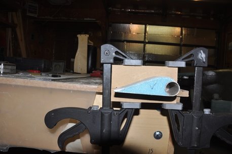
Now that the reference was made, I then set about the task of drilling the holes for the bolts. I had recently bought a drill guide from Aircraft Spruce that has a V-notch in the bottom for clamping onto tubing. The problem is that I can't clamp both sides the tube. So I made a block to clamp onto the back side of the 1x4 to give me a surface to grip a little higher. I marked the drill locations the same distance as the ones on the torque tube earlier (1/2 - 5/8 inches from the end), then I drilled a 1/8 inch hole followed by a #13 and then finally reamed with a #12. The drill guide only had standard inch measurements, so I just used the smallest hole that would accommodate the #13 and the #12 bits. This worked great since you can't use a drill press for this operation. When I was finished, I had two nice holes drilled that an AN3 bolt would fit right into.
In order to secure the nut on the bolt, you have to remove foam from the elevator to access the threaded end. I just cut enough out to have access to the area. The elevator will eventually be trimmed to allow it to fit against the fuselage, so for now I'm not worried about the unfinished surface. I installed the AN3 bolt with two AN960-10L washers, one on each side of the torque tube, and the stop nut. Due to the space constraint, I had to tighten the nut by turning the bolt which is what you normally don't want to do. A small 1/4 inch wrench was able to hold the nut in place while I tightened the bolt down to the proper torque. This was the only one that I had to turn the bolt rather than the nut, but there's no way to properly torque the nut in this case.
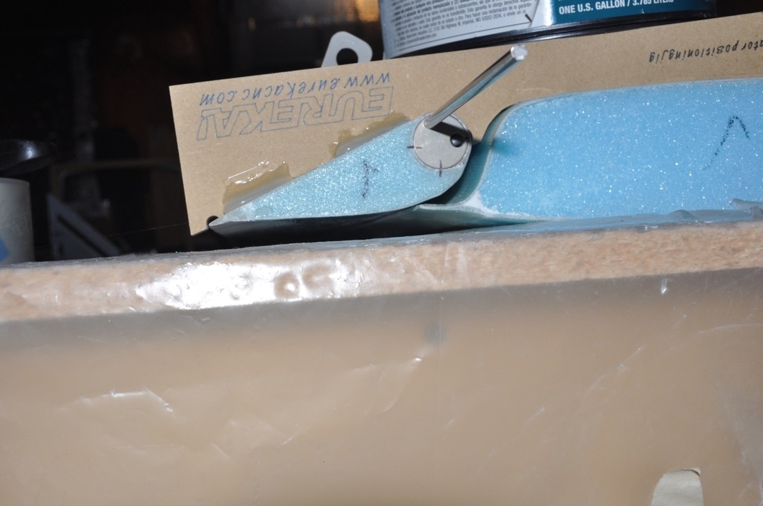
Now that the elevator assembly has been constructed, it's time to install it into the canard. So off the wall comes the canard wing. I left the 1x4s that were on the table to use to prop the wing on. I used hot glue to attach it down to keep it from moving once I was assured the wing was level. I then grabbed the L jigs from Eureka CNC and prepared to set the elevators. The elevator jigs are now made to set the elevators at 15 degrees up instead of in trail. This makes the positioning easier and guarantees you get the 0.2 inch gap when in trail. I did deviate from the plans here. So here's the order that I did things:
A lot of small steps, but it seemed to work well and didn't involve removing the hinge pins which the plans has you do, so I think it was a better method. I left this to cure after I ensured everything was still lined up. I sure hope I got it right...
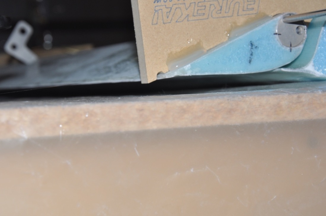
- Trial fit the jigs to the upside down canard to check for fit. I tried the recommended areas, but found that one or two didn't fit as well, so I found other areas that gave a better fit. I then used a laser to check for level placement of all jigs and that they were aligned. Markings were made to properly place them on the canard later.
- The elevator assembly was turned upside down carefully to not bend the assembly. Then it was centered with respect to the canard. The jig locations were transferred to the elevators with a pen.
- With the jig alignment marks added to the elevators, I then attached the jigs to the elevators first using hot glue. This will allow the elevators to be positioned multiple times and doesn't require some funky setup to get them to stay on if the jigs were added to the canard first.
- The jigs were laid back onto the canard lined up to their original alignment markings and the fit was rechecked. I had to slightly re-position the coax cable for the nav antenna to avoid hitting the torque tube. The clearance between the canard trailing edge and the elevator was zero or very close to it. As long as there wasn't interference, it should be good. Any gaps I had were only a few paper layer thickness (the tool I used to check for gap thickness). Once all fitments were checked, the position of the NC-3 hinges were marked.
- The elevator assembly was removed with the jigs still attached to them and the slots were made for the hinges. I drilled one 1/4" hole, then used the fein tool to cut the rest of the slot to remove the glass, then I used the drill to auger out the foam being careful to not put any force on the front side glass. The slots were cut to about the depth shown in the M-11 drawing.
- The slots were filled with wet flox (still has a bit of flow to it) and pressed in well with a mixing stick to ensure they were as full as possible. Don't want these coming out later.
- The elevator assembly was placed back on with the NC-3 hinges all facing down in the install orientation. They won't rotate into the slots, so they have to be rotated before inserting. Care was taken to ensure flox did not get into the pivot point by slowly pushing them in and clearing excess.
- I used a 1/8" piece of aluminum to gauge the height of the hinge in the flox to get the correct height set. Once set and all jigs had reached their previously marked locations, I hot glued them down to the canard to hold them in place for the flox to cure. The edge of each slot were cleaned up of excess flox and filled to ensure the slot was full.
A lot of small steps, but it seemed to work well and didn't involve removing the hinge pins which the plans has you do, so I think it was a better method. I left this to cure after I ensured everything was still lined up. I sure hope I got it right...
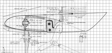
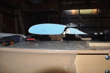
Next up is the first place you get to use some artistic creativity. Once the elevators are attached, the wing tips get to be made. If you go to a canard fly-in, you will notice that there are a lot of ideas on how to make wing tips. I decided to follow what James Redmon did and make the tips sheared and aligned with the wind in cruise. To see his notes on the build, go to www.berkut13.com/berkut61.htm#tips and read up on them. His info covers the winglets, but the same info can apply to the wing tips. The main goal is to align the air flow with the wind direction in cruise, which is about 2 degrees up. In order to figure this out, I scanned the M-11 drawing in then used a graphic program to find the 2 degree angle. I also used pictures of Berkut 13 to help with the design layout. First I did the side profile then made the top and side view since those were easier. For the overall profile, I tried not to flair out the tip more than I had to in order to avoid creating more frontal surface area. When I was happy with it, I printed out the templates to use for marking the canard foam. Hopefully the design works out well.
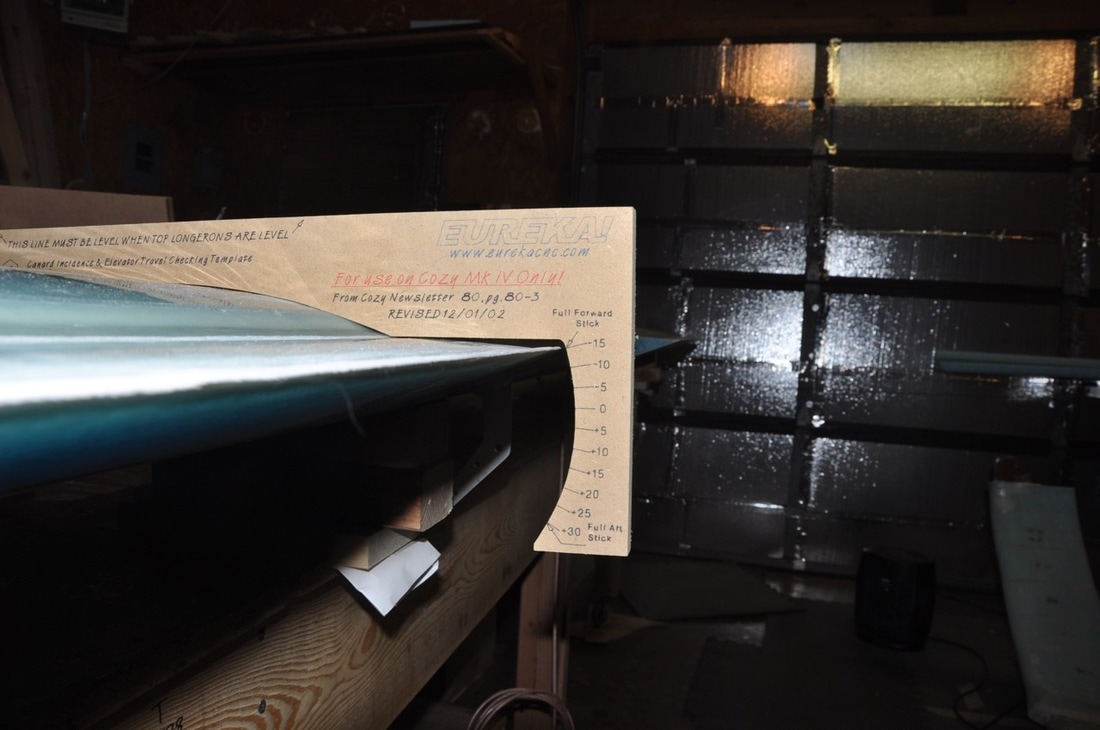
The plans tell you to reattach the jig to hold the elevator in trail, so I used the elevator travel template to find the point where to set the elevator, then blocked it in position to hold that angle. This allows me to set up the wingtip reference.
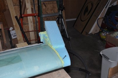
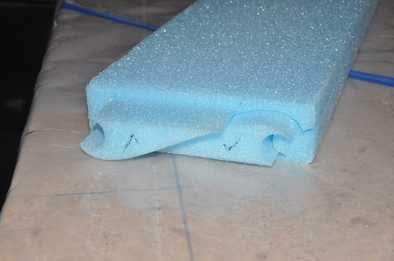
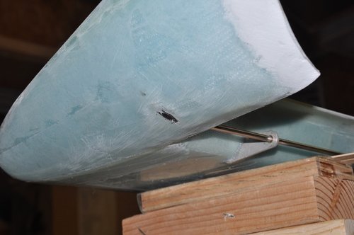
Before starting, you have to add more foam to the ends. The Eureka CNC order includes the foam for the wing tips. However, this foam was shaped for the standard wing tip design. Mine was going to be taller, so I added some extra scrap foam to make it both taller and longer towards the back. I decided to use Great Stuff to glue the foam together. My reasons were that unlike micro it doesn't create a hard spot and should sand more uniformly plus it's fairly light weight. The trick is to spray on the foam, let it expand some, then using a mixing stick flatten it down and spread it out so that the surface is covered in the foam material. It will continue to expand a bit for awhile, just let it sit a few minutes then spread out again. I found that once it wasn't bubbling up anymore, I could the stick it into place and press it in and the foam would glue it down fairly quickly. You can weigh it down or drive some drywall screws to help tack it down if needed. Worked pretty well with minimal expansion afterwards. Once done, I located and drilled out a hole for the hinge pin, then I used Great Stuff to glue on the foam. Drywall screws helped hold the foam in place.
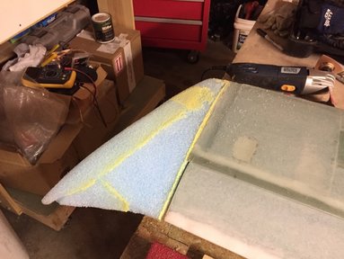
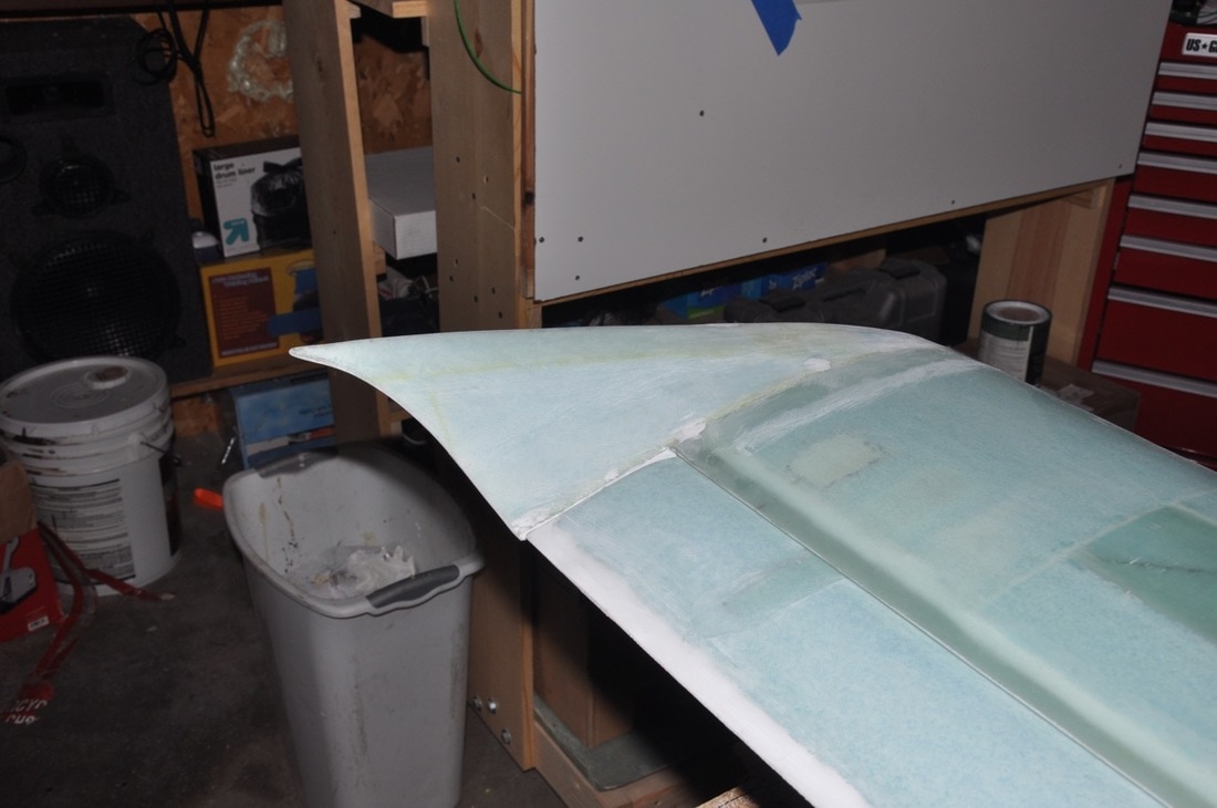
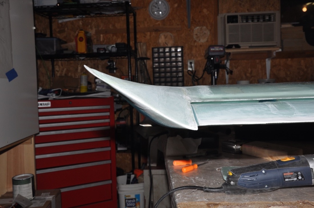
Using my self-made templates, I started carving out the left wing tip. This is the first part that you can really use some artistic creativity in the creation. I used various tools to carve including a hacksaw blade, a sanding attachment for the fein, and sandpaper. The top was sanded to fit the existing canard profile then swept up to the tip. I also started cutting out the top profile and rounding off the top edge. All bottom contouring will wait till the top is done and glassed. To glass over the top, I spread micro onto the foam, sanded the glass on the canard 1 inch for the overlap, then wetted two plies of UNI at alternate 30 degree positions. The top didn't have too much complex curves so the UNI was able to fit. I peel plied the surface and the overlap to smoothing things out and left to cure.
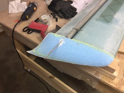
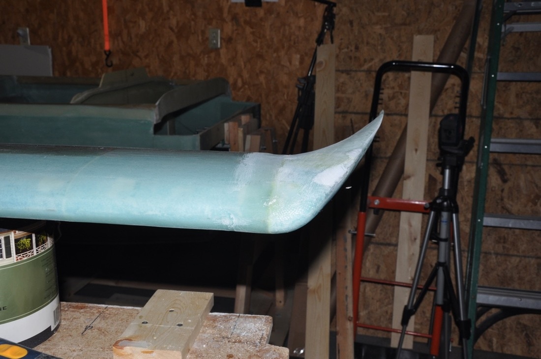
After cure, I trimmed the layup then flipped the canard over to do the bottom side. The foam was cut away to make a 0.5 inch glass to glass bond and the rest of the foam was sanded to have the right shape and to allow the transition. The outside edge was different as I had to transition from a rounded profile to a sheared profile. I used a flox corner for the area from the rounded part to the point where there is a glass to glass transition. May not be the best way, but it's what I came up with. It worked so I'm not complaining much. For the hinge pin hole, I wrapped the pin in mailing tape, then I piped in micro to the hole in the foam to surround it for a channel. After cure, I removed the hinge pin and sanded the micro to fit the foam contour (very carefully). Then I microed the foam and glassed with 2 ply BID as there were harder contours to match, though it might have been possible with UNI. Peel plied and allowed to cure.
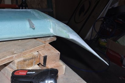
After cure, the glass was trimmed. I filled in the trailing edge with dry micro to allow contouring of the edge where the glass to glass transition was. I then made flox corners and glassed the inside surface of the wing tip that's along the elevator side. This completes one side, so all I need to do is make some templates to try and exactly copy the tip contour to the other side.
The hinge pin was measured to length (60 inches) then the end was ground at an angle to match the wingtip profile. I then drilled a 7/64 inch hole that is just big enough to allow the allen wrench for the set screw to fit in and help pull out the hinge pin. The grinding was done using an angle grinder.
After finishing the wingtips, I added the weights to the elevators. For the inboard weights, I didn't have any bolts at the time, so I decided to 5 min epoxy them to the arms. After they had time to cure, I drilled out the two holes with a #10 drill for AN3 bolts with two AN960-10L washers each and a MS21042-3 stop nut.
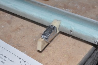
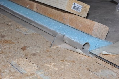
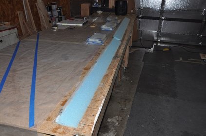
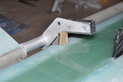
For the outboard weight, the L Jigs are attached so the center of the jig is 5 inches from the inboard wingtip location. I hot glued them in place for easier removal later. I covered the jig with mailing tape to facilitate removal of parts. Then H100 PVC foam was used to make the spacer that is in the M drawings. The weight, made by the Cozy Girrls, was attached to the foam which was attached to the torque tube using 5 min epoxy. After cure, the jigs were removed and the assembly was wrapped with 2 ply UNI strips. I peel plied the ends to smooth them out. As mentioned in the Cozy FAQ, I also added 1 ply BID at 45 degrees to both sides of each weight to give it some extra shear resistance.
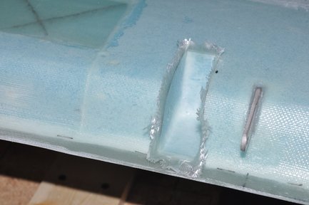
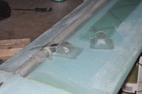
Once the weight assembly was cured, I then marked and cut out the pockets for the weights. I made sure to leave at least 0.1 inches of space around the weight. The foam was removed all the way down to the top skin in order to make sure the weight had room to move the full travel. The foam was microed, and micro was added to the corners to radius them so 1 ply BID could be glassed in each pocket. The glass was trimmed afterward. Unfortunately, despite trying to leave the full room, one weight started hitting right at the 30 degree angle. So I'll have to do something to keep it from hitting.
To correct the weight hitting, I decided to make a stop using a piece of 1/4" plywood. I cut it and angled it to fit the profile of the inside weight arm so that it would stop the elevator at 29 degrees. I had to give up one degree since the weight was hitting at 30, but looking in the archives this was okay. To attach the wood, I floxed it onto a sanded surface then glassed 2 ply BID on both sides. After cure and trimming, the piece was stout enough to hold up to the elevator weight arm hitting.
Suggested in the plans, but not covered, was making covers to avoid ice buildup in the outboard weights. What I did was take a piece of foam and carve it to have a curved profile that would allow the glass to transition easily. I then covered it with electrical tape for release. 2 ply BID were glassed over the plug. After cure, the part was trimmed to leave enough flat area to glue on later. These will get attached after the plane is finished and painted.