Chapter 24: Covers And Fairings
This is an interesting chapter because it comes towards the end of the chapter list, but I'm doing it well ahead of other chapters. Reason being is that while the fuselage is on the rotisserie it is far easier to work on the inside of the fuselage when you can rotate it than to crawl around on the inside
Special Tools Needed
- None yet
Tips And Hints
- This chapter is best done after the controls are in from Chapter 16 and before Chapter 13 is completed. That will allow layout of the armrests better and by not having the nose built the fuselage can be on the rotisserie making this chapter far easier.
- To gain more space inside the fuselage, make the armrests close to the control tubes leaving at least a 1/8 inch gap. Glass the inside, then remove the foam from the side facing area to make a glass to glass bond, then transitioning back to foam as the armrest cuts in. It can add a couple inches of space depending on where you measure at.
- The rear bearing wood blocks can be thinned a small amount if the bearings were mounted as vertically as possible. This along with shaping the arm rests to hug the torque tubes will leave as much space as possible in the back seats where it's really needed.
- There is debate on whether or not to make the arm rests removable. I decided to make them removable for easier maintenance and access to lines, wires, and torque tube inspections. Access panels can be made if there's a desire not to make the arm rests fully removable. If you make them removable, the bearing block will need a re-enforcement added. You will also need a support structure for the rear part of the arm rest.
- The map pocket can be used as a support for the removable arm rest, but will need a few layers added to the top portion to support the loads better. I made a flange on top of the map pocket to support the arm rest better.
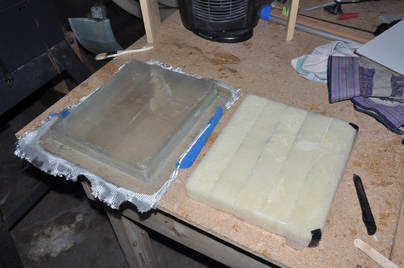
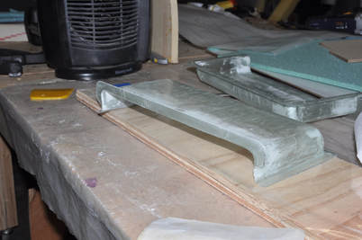
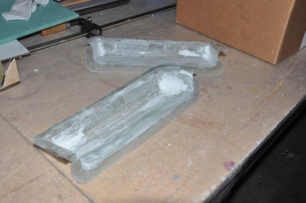
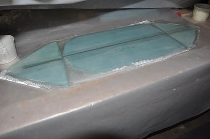
I started working on this chapter while I was waiting to buff the cut ends of my tubing from Chapter 16. The first thing to make is a map pocket. While not many will have maps in the near future, it's still nice to have storage wherever you can get it. Plus, it should be useful for an iPad or similar. First, using some scrap foam I made a plug and rounded the corners. I made mine double wide so I could make both sides at one time. I then covered the top with tape but I forgot to wax it. The wax will really help release the glass later. I then laid up two ply BID at 45 degree angles over the surface, sides, and 1 inch onto plastic to make a flange. This was peel plied and plastic plied to smooth out. After cure, the part was trimmed as specified in the plans. I messed up and made my first one to the wrong dimensions so it was not long enough. I decided to remake them but kept this first one to see if I'll be able to use them in the back (not sure what the width is).
I decided to make my arm rests completely removable. This will require making attachments and reinforcements , but the payoff is greater access to the equipment underneath. There are a few ways to make removable armrests:
- Fully removable one-piece cover
- Glass in the top, leave side removable
- Add in side access panels
- Make back half removable
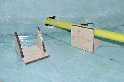
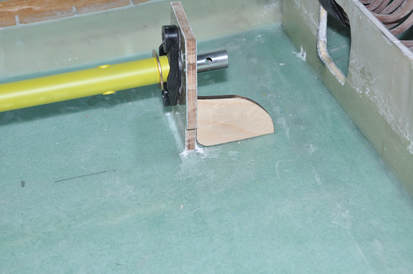
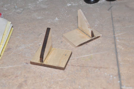
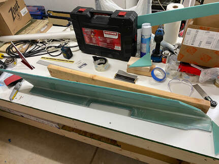
The other reinforcement that is needed is towards the back. From what I have read, the back part of the arm rest gets pressed on hard from people getting in and out of the plane. So I decided to make a fairly substantial support for this area. I cut some triangular braces that were curved to get around the torque tube and one flat bearing surface. Once these were shaped, I assembled the part and glassed the inside surface with 2 ply BID and trimmed after cure.
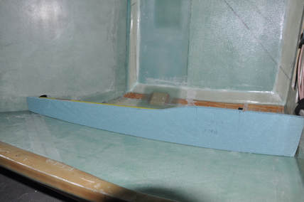
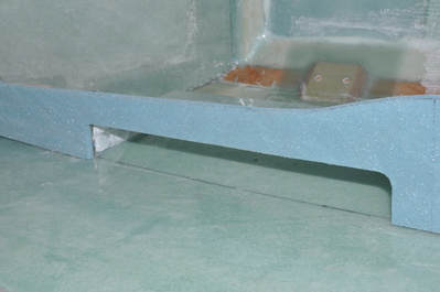
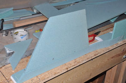
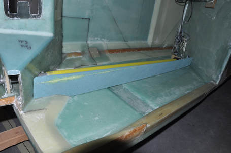
Next comes a point of artistic creativity. If you were to follow the plans method for making the top of the arm rest, there would be a lot of lost space in the cockpit. The plans has the side make a straight line from the IP to the seatback location which eats up a lot of space for no reason. What I did was to leave the foam at the plan's width at the stick area, then after that area I made a nice cured transition to a profile that follows the angle of the torque tube but leaves 1/8 - 1/4 inch gap so that when I attach the arm rest side it won't be rubbing on the torque tube. This method regains a lot of space back that would have been lost. It'll also add some artistic qualities to the interior giving it a more organic appearance (I hope anyway). To shape the bottom profile, I ran a pen along the fuselage side with the point on the foam surface and sanded the foam till the gap between the pen marking and the foam edge was the same all the way across. This was done before shaping the top edge as seen in the picture. More space will be gained later when the inside is glassed and the foam on the sides can be removed for a glass-to-glass transition.
To add extra support for the arm rest from people putting their weight on it, I decided to add a flange to the top surface of the map pocket. This will not only strengthen the pocket opening, but will give a support structure for the arm rest. The map pocket will be floxed and BID taped into place so it will have a lot of bearing surface for the arm rest. With the rear support structure and the front support structure, this should make it very strong with minimal additions. To make the flange, I covered a flat piece of wood with plastic then sanded the inside edge of the map pocket to remove the shine, attached 2 ply BID all around the edge with a 1 inch overlap and one inch hanging off. I then placed the pocket upside down onto the plastic while pushing the remaining BID tape to the outside. The plastic makes a good release layer and the wood creates a flat surface. The overlap inside the map pocket was peel plied to make a smooth transition and all air was pushed out. After cure, I trimmed the flange to 0.5 inches in width. The pocket was fairly stiff and now provided a good bearing surface for the arm rest.
While I was at it, I made an effort to make sure the inside of the pocket was smooth. Since people will be sticking hands into it, it made sense to smooth out the walls some. I used dray micro to fill in the corners where there were some holes from the fibers separating out making the bend and help create a smooth transition. Any rough edges were sanded as well. Should make the pocket more user friendly in the future.
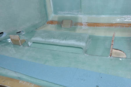
With the map pocket ready and the rear arm rest brace made and glassed inside, the parts were laid out and checked for fitment along the reference line. Flox was mixed up and placed on the mating surface of each part. I also added a couple of drops of 5 min epoxy so the part wouldn't shift while BID taping. The parts were pressed into place and the excess flox was removed or turned into flox corners to allow the glass to transition easily. I tried to make sure the flox inside the map pocket was smoothed out since hands will be in there and it will be hard to get to after cure. All the joints were 2 ply BID taped and all edges plastic plied to smooth the transitions and get excess epoxy out. After cure, the parts were trimmed and sharp edges sanded smooth.
Now that the parts had been installed, the arm rest was tested for fit. All the parts made a nice support for the arm rest. Next, the flange was traced onto the foam, then the opening was marked 0.5 inches within the flange outline and cut out. The inside edge of the foam was sanded to a radius to prepare it for glassing later on to allow an easier transition for the glass. The cutout was close but my map pockets weren't perfectly square so I'll have some fill to do to make a smooth transition.
Next the rear bearing block support was floxed and glassed into place the same way as the other pieces. I didn't have time to do this the same time as the others or I would have. This piece will help support the bearing block as well as support the arm rest.
To aid in supporting the rear arm rests, I decided to make use of my mistake map pockets that I made the wrong side previously. The only issue is that these won't be able to be as deep as the front doe to space constraints. However, a slight pocket could be useful for small items and will add that extra support that is needed. With the controls in place, the pockets were fitted in the location where I imagined the most weight would be placed and the pocket was marked to be trimmed to fit the area. This location ended up being with the rear edge at the start of the fuel sight gauge. My pockets ended up being 3.5 inches in height after trimming to fit the area. I did the same procedure that was done before by laying up a 2 ply BID flange on the pockets and curing on a flat surface, trimming the layup to 0.5 inches, and then floxing and BID taping into place.
Just to ensure there won't be an issue with support and to make sure the rear arm rest is secure, I added a wooden support to the back edge as well. These were made with a single flat piece and one brace. I decided to flox and glass all sides of this in place rather than glassing the inside first. Made for a tight working area but it did free up some time having to wait for a cure. All edges were peel plied or plastic plied for a smooth finish.
I continued building the rest of the front arm rest. This has become a very tedious process due to all the angles and space savings I'm trying to do. I fitted a piece of foam to take care of the angled portion in the rear. I used 5 min epoxy and finishing nails to hold this part in place till it cured. The only section left is the mid area where a complex compound curve is needed. Prior to adding this piece on, I took the top part and pressed it into place over the arm rests and other supports while they had release tape and micro on them. This allowed me to create a perfect fit that will get glassed over to hold in place when the inside is glassed later.
Originally, I was going to make a nice fluid contour from the angled area to the vertical area by the stick to give the arm rest less of a boxy look. Trying to negotiate this compound curve started taking too much effort. Then I realized by looking at pictures of other builds that this area was going to be covered up by the seat pan ribs anyway. So I decided to just continue the angle to the vertical portion and then add a 90 degree face to merge the two together. This will simplify the build and will give the cushion something to hook onto to avoid slipping forward. I'll still generously round the edges to give it a smooth feeling with as little pressure points as possible. I'll also radius the corners to give them a nicer shape as well. I did double up the foam in the vertical areas so that when I sanded away the first layer there would still be foam to support the structure better.
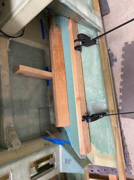
Once the inside of the foam was shaped and all pieces in place, I glassed the inside with 1 ply BID using micro to radius any inside corners or transitions. I also added an extra strip of BID to the area where the torque tube will be so that when I make the glass-to-glass transition with the outside this area will have a little more support. I peel plied the surface and allowed to partially cure. In the fuselage, I covered all the mating areas where the arm rest goes with release tape then when the glass had cured enough to stay put I pressed the armrest into place, weighed down, and left to cure. This would ensure that the armrest would conform to the fuselage correctly and not warp out of place during cure.
After cure, I removed the arm rest and found that some of my glass got pushed the wrong way. Not a big deal, but I had hoped for perfect. I also had some strange voiding on one of my PVC panel pieces. This was the same thing that had happened to one of my sides. It appears me and PVC foam don't get along for some reason. I decided not to worry about this voiding as this piece was not structural and wasn't worth redoing at this time. I'll fix the larger mistakes, but move on. Perhaps my micro was too dry. I'll have to test this when I do the front.
After trimming the part and refitting, I was able to get a fairly solid install. To help secure the part in place, I made two 1/2 drillings in the surface over the areas where the wood blocks are located but I stopped before cutting the inside fiberglass layer. This created a cavity that I then filled with flox so I could drill for a screw. I counter sunk the micro to place the screw head flush. I had to use a Truss head type because the angled head didn't come in a size long enough to attach to the wood supports. I used two on top: one on the front and one in the back. These will be covered by a removable foam pad that will go over the armrest at a later date. The only other thing that I need to do is make a catch lip at the bottom to help hold the armrest in place which I'll get to later. Sadly, this thing took two weeks to do because of all the angles and figuring out geometries. Granted I wasn't on it heavily, but it was still annoying.
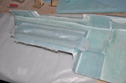
Moving on to the rear arm rest, this one should be simpler due to less geometry changes to make. First I cut the top out of PVC and started the shaping process. The plans shows a two piece arm rest but I went ahead and made it full length. The bearing block already has a support piece added and I desired the ease of access and maintenance that a fully removable armrest will provide. The ends were angled to match the slant of the front seat and the landing gear box. It was also cut to ensure clearance was left for the torque tube. I had to add some slivers of foam because it ended up being too close. My arm rest profile ended up with a bit of a side curve. Might add a bit of artistic flare to it. I then cut the side piece to be long enough to clear the bearing block and ensure there would be room for routing wires. These were then 5 min epoxied together and held in place with finishing nails till cured.
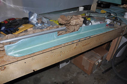
After cure and removing the nails, final shaping of the fit was made and clearance for the torque tube checked, I glassed the inside with 1 ply BID placing a strip along the corner to help strengthen it when the foam is removed. The surface was plastic plied and all edges that would contact the fuselage were trimmed flush with the foam. After letting the glass set up a bit, I pressed the piece into place to ensure it cured into the right shape. After cure, the plastic was removed and the rest of the excess glass was trimmed.
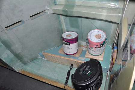
Before adding the slanted side portion to the rear arm rest, I wanted to get the rear seat bulk heads into place for fitment issues. I cut the foam out and fitted to the fuselage. Then I micro covered the surface and glassed 1 ply BID to all pieces on both side. I used plastic ply to make a nice smooth void free and flat surface on both sides and left to cure.
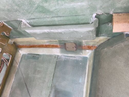
Something I decided to do while I was able to was make some simple covers to close up the torque tube area. It occurred to me that this area was open to the holes for the torque tubes and would allow air to bleed into the cabin. I just carved them to fit, glassed both sides with 2 BID layers, then floxed and BID taped them in. I took the tubes out for this to make sure I wouldn't drip epoxy or flox onto them. This will cut down the amount of ingress from outside air and may even keep the cabin a little quieter.
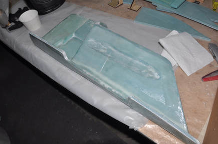
FINNALLY!! After 4 years due to the move and having to build a shop and a pandemic, the build begins again! First thing I did was remove the peel ply from the inserts in the gear leg box and trim the excess. Then I moved on to the rear armrest that never was finished. I attached a piece of foam at an angle that would allow space for wire runs while minimizing the loss of space for the passengers. This was attached with 5 min epoxy. I then proceeded to shape the foam till I had a fit that matched the fuselage profile.
After getting the profile done, I then prepped the glassed part by sanding, micro the surface, then laid up the 1 ply BID and covered with plastic ply. This would have been better if I had done the whole armest in one piece and probably will do this for the other side. To ensure it had the correct shape, I placed packing tape on all the contact points on the fuselage then pressed the part into place with weight and clamps to cure. I waited till the epoxy was already setting so the glass wouldn't come off while curing.
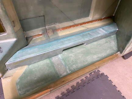
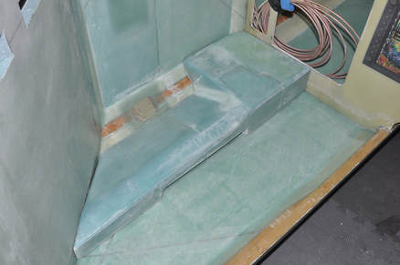
After cure, I popped the piece off, trimmed the excess, then did what I had for the front and shaved off what I could of the foam that was on the vertical side. The idea here is to remove as much space robbing material to give the back seat more space. 3/8 inch isn't a lot, but it certainly doesn't hurt. I had also reduced the wasted space by following the contour of the torque tube and only coming out as much as necessary. The edges were rounded to make them softer on people and to allow the glass to be laid up over them better. For the bottom edge, I made a 1/4" flox corner in order to give it strength. 2 ply BID were laid up over the top and plastic plied. I should have done a separate piece of plastic for each panel but I didn't (I'm a little rusty after 4 years of no building) so I got some wrinkles in the finish. They're minor, but it could be better. This again was clamped into place with tape release and left to cure. Afterwards, I trimmed the piece and checked the fitment. It fits well without anything holding it in place.
I decided to go ahead and add the rear seat bulkhead now that the armrest cover was made. I had made the pieces awhile back. After trimming to fit the profile and laying out the lines where it's suppose to go, I floxed and BID taped it into place. I made support blocks to hold it in place while curing. All joints were plastic plied for a smooth transition. After cure, the excess was trimmed.
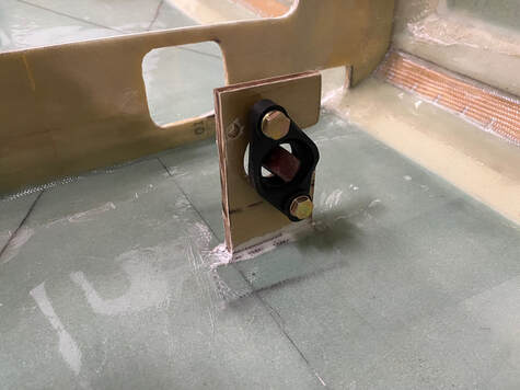
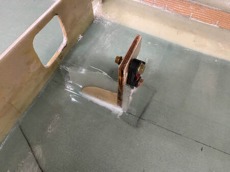
Before I was done with the right side, I needed to glass some retention tabs for the arm rests. Due to making mine removable, I had to devise options for holding them in place. I know that I will screw down the armrests at the top but haven't quite decided how I'm doing that yet. For the bottom, I glassed 2 ply BID tabs at different locations that will hold the bottom in. I did this by taping off the part to add release, then sanding and laying up the BID 1 inch onto the fuselage and 1 inch onto the armrest. After cure, I popped the part off and trimmed/sanded the tabs to shape. With the tabs on, it fits very well and should only need a couple of screws to hold it in place during use. You can see one tab on the left within the floor area and two more on either side of the seatbelt attachment point.
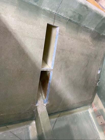
I decided it was time to finish up something I never did finish and that was opening up the Seat back holes. I used a flush router bit to trace out what I could of the pockets to cut it open flush with the seat back brace then using the multi-tool I cut away the rest followed by finish sanding. It was nice to see these spaces again. Remember that I made my 3 inches instead of 1.5 inches which will be much more useful (mostly for water). For the upper hole, I rounded off the corners to prep for glassing the exposed foam and provide a smooth transition. For the bottom hole, since this will get covered up, I'm making a flox corner and will just glass the exposed foam. to give it support.
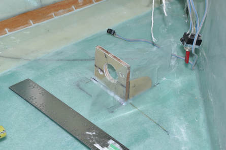
I started preparations for the pilot side arm rests now that the passenger side was done. I first drew the reference lines using the plans and the other side to define where the points were. One thing I decided to do was to cut the front bearing block down so that it would be flush with the foam surface. The plans originally has you make the bearing block flush with the top surface of the glass because the armest is permanently bonded into place. Since I'm making my completely removable, I don't need this feature. This block was installed prior to the move so it was just a matter of trimming it to the reference line. This will make the pilot side armrest easier to fabricate.
Next I added the bearing block support which helps to stiffen it since I'm not building in the armrest. This was done the same way as the last one with a piece of the birch ply cut to fit the front side of the block, then it was floxed into place. The joints were 2-BID taped and the edges peel plied (plastic ply in this case). The same treatment was also given to the rear bearing block.
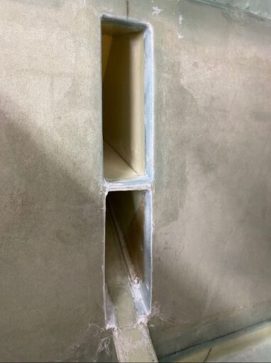
While I was here, I finally decided to finish up the map pocket and pass-through area. For the map pocket, I rounded the edge with a 1/4" rounding bit on my router and then sand paper for any areas the bit couldn't reach, mostly the top. This gave a nice rounded corner that would be easier for the glass to lay down on and would be softer to the hands going in. For the pass-through, I just made flox corners as I figured this will eventually be covered up with the throttle quadrant cover and wasn't something a hand would be reaching into often. I then 2-ply BID taped the perimeter from the outside wrapping over the curved area and onto the inside of the pocket area. I plastic plied all the joints as best as I could to keep the surface nice and smooth. This covers up the exposed foam and makes a nice smooth transition into the map pocket.
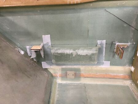
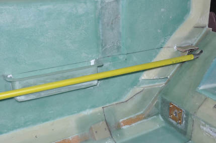
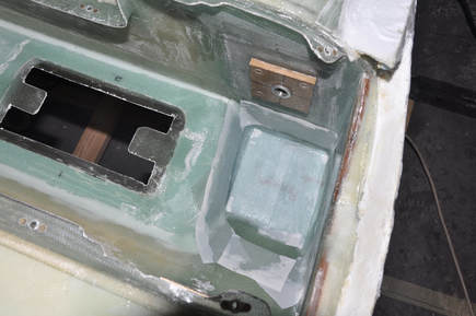
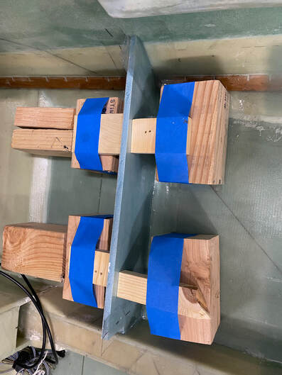
Next I moved onto adding the map pocket and the rear brace support for the pilot side. I marked out the locations of both. The map pocket is placed in the plan's location. The rear block was placed the same distance that the previous one was (3.5 inches from the map pocket I believe). The installation points were traced down for reference. After ensuring the sides were well sanded where the parts install, the mounting points were retraced then were installed with plenty of flox. The excess was removed leaving enough to make a fillet transition from the part to the side of the fuselage. The edges were then 2-ply BID taped. I ended up using peel ply for most of these because the joints aren't super flat and peel ply conforms better. Note that the picture makes it look like this was done upright but I currently have the fuselage on the rotisserie and it's sideways so these parts are laying down on the side. So much easier than it would have been if the chapters were done in order.
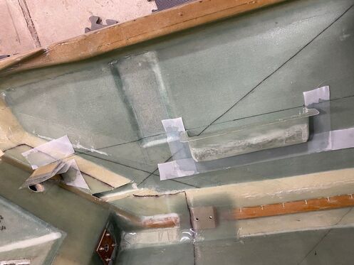
While the front parts were curing, I went ahead and decided to install the rear pilot side parts as well. I did the same steps of marking the install locations, sanding the sides and pieces, then wet floxing in place, removing the excess, then 2-ply BID taped all the joints and peel plied the edges for smoothness. Note that for the rear bearing block I glassed the entire top to make a nice flat surface for the armrest to sit on. You can tell in this image that the fuselage side is facing the floor.
|
Next: Chapter 25: Exterior Finishing
|
