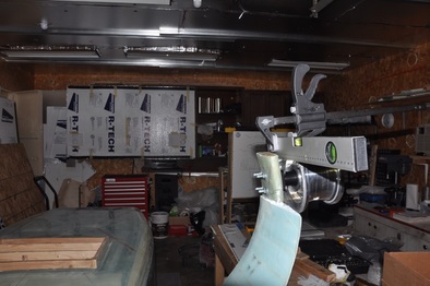
Chapter 9D: Axle And Wheel Installation
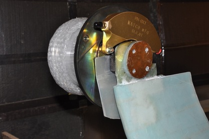
With the landing gear now mounted, I can turn towards mounting the axles and wheels. This will be the last point where corrections can be made to get the wheels located at the correct height and distance from the nose. I chose to go with the Matco Wheels and Brakes as they come highly rated by others and they are made just a few miles from my house. I got to tour their facility and was highly impressed with the operation.
Special Parts List
- Matco Parts: Wheel and Brake: WHLW51LXT Axle: WHLAXLE1A Master cylinders (x2): MCMC-4
Tips and Hints
- Bernard Siu created some templates for cutting the gear leg to fit the Matco brake installation. They can be found on the forum.
- It is advised to run stainless steel braided flexible brake line down the leg to the brake due to the movement in this area. Nyloflow has had issues with breakdown and falling apart if not well protected.
- The gear leg should be protected from heat generated by the brake rotor. This usually involves wrapping the leg in fiberfrax and wrapping with aluminum tape. It's also advisable to add an aluminum heat shield that will reflect heat from reaching the leg. Again, Bernard Siu made a template for one.
- There has been some talk of various gear legs spreading out when the weight of the craft was placed on them causing the axle alignment to go out. Some of the theories were that the gear leg may not have been post cured. So just to make sure mine was good, I set my finished gear leg in the un-insulated garage to post cure in the hot Utah summer to post cure. Might be worth doing and the effort is low.
So the first item up on the list is to locate the axle centers. The centers will be located at FS 110 and WL -19.0. FS 110 is given in the plans. WL -19.0 is found on the back cover of the plans. If you properly located your strut front edges at 108.25, then you should only have to measure back 1.75 inches from the front edge to get your FS position. I had one side that was 1/16 inch more forward, so I added this to the measurement so that both axles will be properly placed. May not matter, but why not. In order to get the WL level, I clamped my smart level to the upper longerons, made sure all was level, then measured up from there. The longerons upper surface are at WL 23. So 23 + 19 = 42 inches from the longerons to the axle location. I used my self-leveling laser line to set it at the 42 inch mark so that I could mark both sides of the strut. After marking both sides, I verified that both axle locations were level with the fuselage level and verified that they were at the FS 110 with the floor lines.
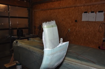
Next, I wrapped the strut ends with 3-ply BID that are used for the re-enforcement for the axle bolts. I wrapped an 8 inch piece that was tall enough to fit the exposed strut so that it would wrap from the trailing edge around to meet the ends on the leading edge. I then peel plied the entire layup to smooth it out and provide a bonding surface for the axle. After cure, I trimmed the glass to be flush with the strut end. I decided it was easier to add the layup before I cut the strut to fit the Matco brakes.
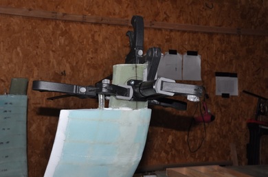
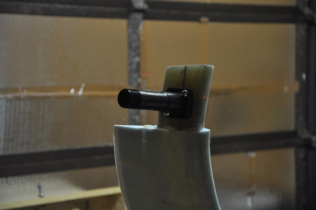
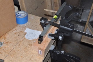
Next I re-verified my axle center markings to make sure I had them in the right spot. I used my self leveling laser level to check that they were matched on both sides. I then drew a horizontal and perpendicular line that I could use to center the axle with. To center the axle, I clamped the axle with one clamp, then measured the sides to see if the line drawn on the strut was in the center of each side. Move the axle a bit, remeasure, move again till all four sides were lined up. I then used several clamps to hold the axle in place and as parallel as possible to the surface. The strut still has some curve at this location, so you have to do your best to set the correct incidence angle. With that set, I used the axle holes as a guide to drill the strut for the bolt holes. After one hole was done, I temporarily bolted the axle in that spot to allow removing a clamp to drill another hole. This went on till all four were drilled.
After drilling one side, I drilled the other side in the same fashion. Just as a double check, I verified that the axles were parallel with each other using the self leveling laser. Both were able to match with small tweaks of the bolt settings, but more importantly they had the same angle to the strut face. Good so far.
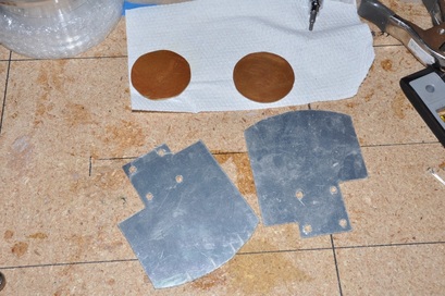
There are a couple of aluminum parts that are needed for the wheel install. One involves a backing plate to bolt the axle to. The plans have you do a square piece, then shape it to match the strut cutout that you will have to do later for the caliper. I decided to follow Bernard Siu and make them circular. I'll admit, I did these free handed on the bandsaw so they are not perfect like a hole saw would be, but I couldn't justify spending $25 for a hole saw. These were cut from 1/16 inch aluminum (per plans). I used Bernard's templates to draw the cut line. One side of each disk was sanded to roughen it for bonding to flox later. The other part isn't discussed in the plans. Due to the heat of the brakes especially during hard braking, the strut leg can soften and collapse. The plans has you wrap it with fiberfrax and aluminum tape, which I will eventually do, but as an added coat of protection a heat shield is placed between the leg and the brake disk to reflect heat away from the strut. Again, Bernard has templates for a nice design. Due to the clearance issues in this design, I went ahead and got a hole saw to make sure the hole was just enough. After cutting, I alodined the backing disks only. The heat shield was left alone because I wanted it to stay as reflective as possible. The heat shields aren't completed yet in the picture, but you will see the final work later. Now we're about ready to install!
Update!! Bernard Siu was nice enough to allow me to post his drawings on my site. So they are here for your use. Please note that I did not make these and am just posting them for other builders to make it more accessible. Thanks again to Bernard for making the drawings and for allowing me to post them.
| brake_template.pdf |
| heat_shield_template.pdf |
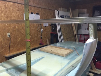
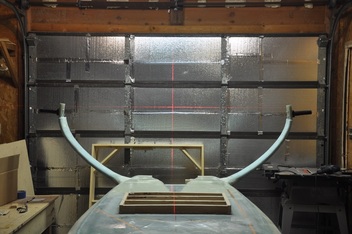
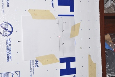
Next up was setting up the parallel panel for measuring toe-in. I didn't have a lot of things to use around and the walls are all covered with objects, so I taped up one my former foam walls from the now dismantled heat room. I used other pieces of foam to shim it as vertical and straight as possible. I then placed a laser line straight down the middle of the fuselage and marked the location on the wall. I then picked my references on the strut to figure out how far apart from the centerline they were, then I measured the same distance on the board. The reason for doing this is to check for parallel placement. If the fuselage centerline is perpendicular to the board, then the measurement distance from each side of the strut will be the same. If it's crooked, one will be longer than the other. Make multiple adjustments and measurements and eventually you get a setup that's parallel.
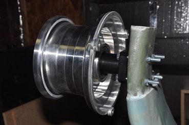
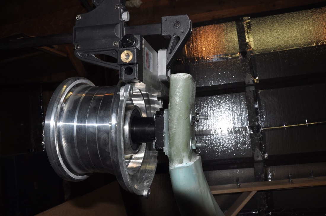
Once the fuselage was parallel, I needed something to make my references from. I decided to follow Bernard Siu again and use the rim. This required removing the disk and caliper (I have not cut the strut to make room for the caliper yet). Once done, There is now a flat surface to use as a reference. I measured the distance and height between the centerline of each rim (where there would be the least movement from toe adjustments) and recorded this as the reference mark. Then all that will need to be done is calculate the amount the laser (I'm going to use a laser rather than the plan's method) will need to move inwards to reach the desired 0.25 degrees of toe in.
In order to accurately do this adjustment, You have to find the error in your laser. To do this, you do the following:
- Set your laser at a distance from a flat vertical wall. Use something that will allow you to set the laser in the same location with the same orientation. Setting it at the same distance you will be using it will help, but is not necessary.
- Record the location of the centerpoint for your laser.
- Turn the laser 180 degrees so the bottom is on top now.
- Mark the location of the laser centerpoint.
- Check one or two more times to verify that you have a good repeatable measurement.
- Measure the horizontal distance between the two points. Divide by two in order to get your laser offset. Make sure to note the direction of the offset with reference to the orientation of the laser.
- You can calculate the angle of offset or you can take this measurement and divide by the distance that the laser is at and get how much to adjust per distance. Either way works.
- One other thing to get is how far the laser is from the side of the level. I turned on the laser and measured the distance from the center of the laser to the edge of the level in both directions. They were the same, so I now have my offset of the laser from the level also.
| axle_alignment.xls |
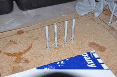
With the alignment of the laser calculated, I turned towards installing the axles. I first taped the bottom and sides of the axle base with mailing tape. This will release it from the fox. I also waxed the tape surface and the bolts to avoid them getting stuck on as well. I just used inexpensive store bolts so that I wouldn't ruin good bolts doing this. The area where the axle attaches to the strut was sanded to ensure the proper bond surface. I then mixed up some fairly stiff flox, spread it onto the axle surface (with tape on it of course) then installed it. I reattached the wheel rim, added the laser, then slowly tightened the nuts till the axle was fairly close to the strut surface and the angle was set at the 0.25 degrees of toe in that is needed. Once set, the excess flox was cleared away and it was left to cure. Periodically, I would recheck the alignment to make sure it didn't change.
After cure, I rechecked the alignment and found it was still right where I left it. So I removed the bolts and axle, peeled away the tape, and reinstalled the axle to recheck the alignment. For an unknown reason, the alignment shifted, a lot. So i spent several days trying to sand the flox pad into shape, refloxing the axle, and rechecking till it was right after the tape was removed. I never could figure out why it kept shifting from perfect, but it did. One side took many attempts to get it. Never saw anyone else mention the issue, so there's something going on that I don't see. At any rate, I did finally get them set to the proper toe in and aligned vertically with each side.
UPDATE: I believe what may have happened was that even though they had a whole day to cure, the flox pads weren't cured enough and they deformed a bit under clamping pressure. The last one got to sit for two days before I got back to it and it was fine. So make sure they're well cured before removing. You can just barely make out the laser mark that is just barely to the right of the alignment line. This is very small and the fuselage might have moved slightly anyway.
UPDATE: I believe what may have happened was that even though they had a whole day to cure, the flox pads weren't cured enough and they deformed a bit under clamping pressure. The last one got to sit for two days before I got back to it and it was fine. So make sure they're well cured before removing. You can just barely make out the laser mark that is just barely to the right of the alignment line. This is very small and the fuselage might have moved slightly anyway.
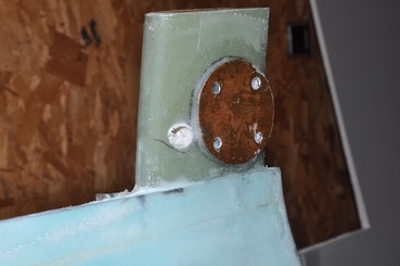
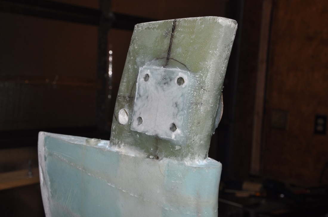
With the flox pads out of the way, I could finally turn to the backing plate. Most install this at the same time as the axle install, but I didn't want to have to mess with it much if I had to change things. So once the holes were set and the flox pad was set, I taped the metal in place tight against the strut, then put my drill through the axle mount holes and dimpled the surface of the backing plate. This marked where the holes needed to be drilled and I finished on the drill press. After deburring and checking the fit, some holes had to be slightly widened in order to accommodate the bolts, then relatively dry flox was spread on and it was pressed into place on freshly sanded surface. I did my best to get it parallel with the axle flox pad and ensure only a minimum of thickness was added. The strut end was where the plate was the closest to the strut surface. The bolts were re-waxed and inserted and the assembly was allowed to cure. I redrilled the holes to clear out any excess flox and inspected. Looks decent enough, so moving on.
Next up is trimming the gear leg ends to allow the brake caliper room to clear. I had used Bernard Siu's template to trace out the general cut line. Then I used a 1/2 drill bit to drill away the low spot where one of the brake caliper bolts rests. This was easier than trying to cut it out, leaves a nice rounded profile, and was quick. Probably could use a bigger drill to match better, but it'll get me close enough. I used a combination of the Fein tool, scroll saw, and sanders to remove the rest. The backing plate makes a good judge of the profile to cut. Also need to make sure you can get to the two nuts that are near the strut.
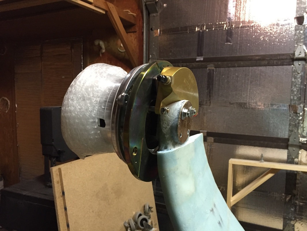
Last thing to check is the clearance between the caliper and the strut end. The caliper slides to adjust for pad thickness, so you want enough space between it and the strut to avoid binding the brake. So I attached the whole wheel to get an idea of what I had and make adjustments till I had enough clearance. Once I had the clearance, I was done with the strut shaping.
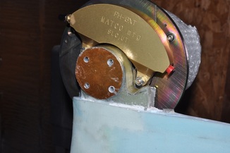
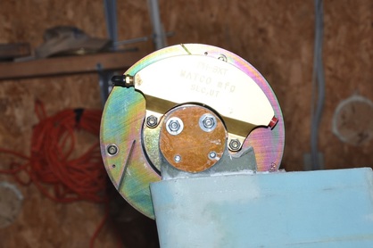
One more thing before I can call the wheel install complete: heat shields. I had cut out the profile, but I still needed to cut the hole from the center. These heat shields work by slipping over the axle and getting bolted down when it does. It also has to be bent to clear the brake disk. I used a hole saw to cut the hole out for the axle. Then I fitted it and adjusted for the brake disk clearance. The idea is that it will shield the strut leg from the radiant heat coming from the disk during hard braking. I just put one bend in to clear the disk. However, I found that the heat shield was not centered. What I didn't realize was that Bernard's templates require the axle bolts to be in line with the strut sides. I made them in line with the ground, so this shifted it slightly. It should still work and I'm still going ot wrap the gear legs later with fiberfrax and aluminum tape anyway. Obviously, I will need to cut away some of my gear leg fairing, but that will wait till I one day do wheel pants (going to put that on hold for now). With that, the wheel install is complete!
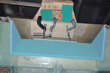
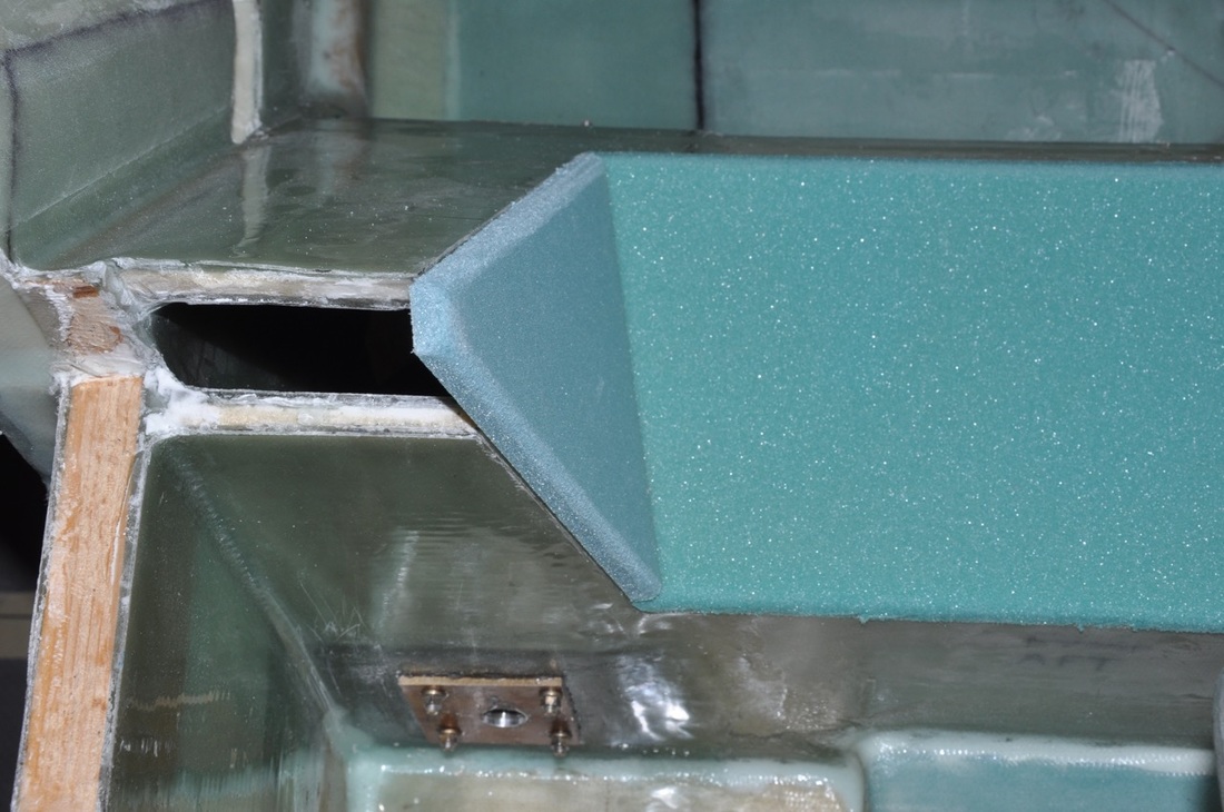
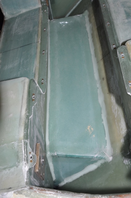
One more thing that remains is to enclose the gear leg bulkheads. I'm going to put off adding the brake lines till I do Chapter 13, but to ensure I can get access I made my access covers larger and rectangular. I also figured this would make it easier to build attachment flanges. So the first thing was to cut out the 3/8" PVC foam to shape. I made the long bottom piece by the dimension in the book, then trimmed to fit. The front edge was cut at a 45 degree angle to match the front gear leg bulkhead. For the side pieces, I held a piece of foam to the sides then traced the outline of the bulkheads to get the proper shape. Once everything was fitted correctly, I glassed the bottom side with 2 ply BID, then after cure and trim, I floxed them into place. Any part hanging over was sanded flush with the bulkheads for the next step. After the flox cured, I sanded all the joints and applied 2 ply BID tape to all the joints with peel ply to smooth them out.
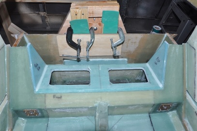
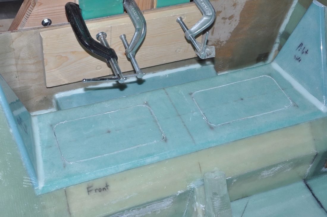
Next step is to glass the top of the box. This step is done so that you will glass the surface and overlap the joints for a built-in BID tape. The foam received a final sanding to get it to the correct shape and flush with the joining surfaces, sand all overlap surfaces, then micro and glass were applied. The surface was covered with plastic and squeegeed flat including all overlaps for a nice smooth transition. After cure, I cut out the access holes in the box using the fein. Space was limited and I was unable to use a scroll saw. I made mine square to make more access room for later work.
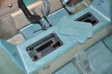
After cutting out, I taped the bottom and sides of each piece with packing tape and electrical tape, attached them back into their holes flush with the surface, then rotated the fuselage (still on the rotisserie) so that I could get to the backside of the cutouts. I used 2 ply BID 1 inch wide and applied half an inch to the box and half to the cutout to form a lip. I added 6-ply BID to the centers of the short sides to attach two nutplates per cover. After cure, I trimmed them up (not the neatest job, but they aren't going to be visible anyway). I have to get more nutplates, so I'll add those later, but for now, I'm calling this chapter done and moving on. Time to build a wing!