DIY Cupless Aviation Headset
I'm a big do-it-yourself person (if you couldn't already tell), so when I found out about building my own aviation headset I was on board. There was the added bonus of it being smaller and lighter as well. This project was originally created by Nick Ugolini (you can see his writeup on his website). There's also a great writeup by Drew Chaplin on his website. Both of them were able to start with a used headset. I, however, didn't have that luxury, so this documents how to build from scratch. Having an older headset will save on some of the cost, but most of the cost I find comes from the headsets themselves. Like the builders before me, the Comply tips work really well and were more comfortable than the included tips.
Here's a list of the materials you will need to complete this project. Note that if you have an older headset several of these parts can be used from it.
- One set of Shure in-ear buds. I used SE215 as this seem to be the current equivalent to the Shure EC3 that was used by the others. You can get used versions of the EC3 but I decided I wanted to have new and the EC3 weren't available for cheap. These were about $100 on Amazon.
- Set of Comply TX-100 Sound Isolation tips. I also got these on Amazon, about $20. I didn't know what type to get, so I went for the max sound isolation versions. Note that the TX-100 fit the Shure SE215. If you use a different ear bud, then check the fitment chart to get the right ones. I also bought their multi pack to find out which size I needed. At first the small actually fit the best. However, on another day they weren't sealing correctly, so my ear opening must be fluctuating in size a bit. so I switched to the medium to make sure that I would have a good seal. I haven't worn them all day yet, but at least I now know what size to get from now on. Unless you know, I would recommend the multi pack to find your size, then just buy that size from then on.
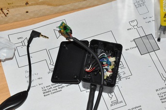
- Shure EAADPT-KIT in-line volume control. This actually comes with a 1/4" plug adapter and an airplane adapter, however I just wanted to volume control part. You could add a potentiometer to the circuit, but liked this idea in case I want to use the earbud for something else. It's also one less hole I have to make in the project box plus it got a bit crowded in there. .
- One microphone. I purchased the one on Aircraft Spruce that has a built in noise filter circuit. Aircraft Spruce Part # 11-04838, $30.
- Two audio transformers for matching the impedance of the headphones to the aircraft system. These aren't always needed, but since I know I'm going to be in other planes for awhile I decided it was best to go ahead and add them. Radio Shack Model # EI-19 part #273-1380
- 0.25 inch stereo jack. You can buy the jack itself, or you can buy a 0.25" jack cable and get the jack prewired, strain relieved, and a length of wire already included. Amazon had a 6 foot for cheap but with a hefty enough cable to be resilient.
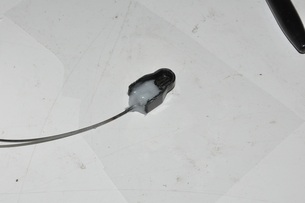
- 0.206 inch Mic Plug - Aircraft Spruce sells this plug that you can connect wire to. Part # 11-00702, $7.00
- Project box, plastic. Got mine at Radio Shack. I got the 3" x 2" x 1" as I wanted to keep it as small as possible. Everything should fit just fine in the box. Catalog # 270-1801, $4.
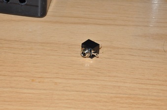
- 3.5 mm stereo plug socket. This gets used to plug the headset into the circuit box. Technically since I'm going to make mine permanently attached for the sake of cables, you could leave the ear buds separate and use them for other things which is why having the socket on the outside is useful.
- Assortment of heat shrink tubing. Adhesive lined would be good to better seal some of the connections, but not absolutely necessary.
- Soldering iron and solder. You can also use crimps if you have the right type and they're small enough to fit within the plug housing.
- Piano wire. I used 0.062" diameter stuff. Nick listed 0.045" which would be lighter, but it looked extremely thin to me. I might change my mind later, but for now that's what I have. You can get this at hobby stores that sell RC models. This will be used to make the frame and mic boom.
- Also helpful would be a prototype circuit board. I didn't use one for the first build but kind of wished I had.
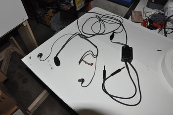
The basic ayout is this: you have a wire frame that hooks around your ears with an extended mic boom on the front. The ear buds hang off the sides to go in the ear. The wires then travel out the back to a circuit box that houses the mic filter, audio transformers, and connections to go to the airplane plugs. Simple, light, and non intrusive.
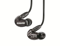
On with the build! First thing is to figure out which tips are going to fit you well. That way when you start mocking up the frame you won't throw things off by having a different fit. As I said, I found the small size worked best for me. They are inserted by compressing the foam, then placing in the ear and holding it in place till the foam fills the area and holds itself. It took a bit to find the right angle that it needed to fit at, but once I did it was no issue.
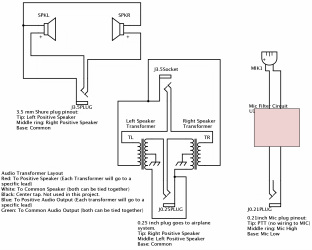
Here's a schematic of how I connected the system. I used Digikey's Scheme-it, which was free. Not the easiest to use, but fit the bill and was able to work well enough. I also included a downloadable PDF that will probably print with better quality. Basically, you have your headset that connects to the audio transformers (if needed) and to the airplane's output. Note that the left and right speaker positive connections swap from the 3.5 mm jack to the 0.25" jack (don't know why they couldn't stick with one standard). The Mic is just a straight connection where all you're doing is making the wire longer. I decided to keep the filter circuit as it wouldn't hurt anything and may have some items that help drive the mic better anyway. Most electret mics needs at least a capacitor to help drive them, and since the board was already with it I might as well use it. Note that the colors for the audio transformer are based on the one's from radio shack. If you get something else they might be different coloring. The headphones are on the secondary side.
| aviation-headset-1.pdf |
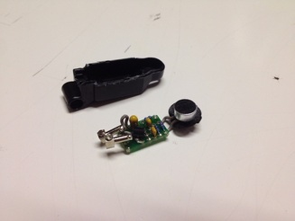
After that it was time to direct towards the circuits and components. I took apart the microphone case in order to get at the internals. The case came open with a gentle prying with a utility knife. Be careful when doing this so you don't cut the wires. Once off, you will find the electret mic and the hardware. It's just sitting inside the case by friction, so it comes out with a little prying. First thing to do is figure out where the positive and negative are. In actuality, it probably doesn't matter much, but since there is a filter circuit it's probably best to hook it up right. There's no notations on the case, so it really may not matter, but I like things to be right. The mic will have the negative side attached to the mic case. You can see leads going from one of the solder pads to the case: this is the negative. After that, it takes some tracing to find the positive and negative on the circuit outputs. What you will do is cut the wires from the board to the mic so that only the mix will be on the boom. The circuit will reside in the circuit box. Wire is added to the end of the mic wires and and extended to the box. I had some two-lead multi stranded wire on a spool that I used for this. The connections were soldered and heat shrink to protect. Remember that you have to have the heat shrink on the wire before you make the connection or it won't be able to go on afterwards.
For the headphones, I elected to try not to modify them as much as possible. This will also make them easily replaceable as they're the most likely to get damaged. So I added a 3.5 mm stereo jack to the box for them to plug into. The wiring for the transformers took a bit of reading, but it was fairly straight forward. Basically, for the type of transformer used the Green and Blue will go to the headphones, the red and white go to the airplane, and the black is not used. I tied it off for the time being, but if problems arise, then it might need connection to ground. It doesn't matter what color you use, but you want the positive on one side to match the positive on the other side. For this case, if you use Blue as the positive connection, then the Red will also be positive. The ground (or common) from each side is tied together, so the green wires will attach to the common of the ear buds and the white wires will attach to the common of the airplane plug. The left and right positives will stay separate.
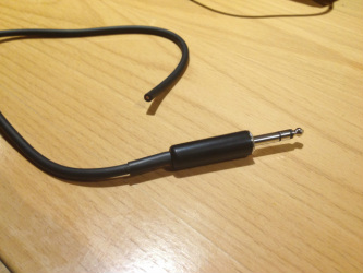
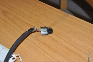
The mic plug uses a 0.21" plug. I bought an adapter from Aircraft Spruce that allowed me to solder wires to some leads. I then heat shrinked the tubing to secure the wires and dress up the exit a bit (Image to the left). Although I bought a 0.25 inch plug to solder the audio wires to, I decided to just cut some length off a 0.25" audio cable with the plug already attached. The interesting thing I found out is that standard headphones put the left speaker on the tip of the plug, but 0.25 inch plugs have the right speaker on the tip. As long as you keep the wires straight as to which is which, it'll work itself out, but if you find your channels are flipped that would be why. In order to solder and heat shrink the connections, I had to leave enough length of wire to pull it through the holes I drilled in the box to work with, then strip enough insulation to allow for adding heat shrink. Again, using a solder board would have been easier I think.
One issue I had was trying to figure out how best to hold the wires in place so they don't get pulled from the box. I used small zip ties as a stop to keep them from moving in or out of the box. I later tried to make a strain relief with black silicone on the outside, but was unsuccessful at making a pretty covering. It is however protected. I'll have to find a better way next time. I think what I would do next time is build up two - three layers of heat shrink on either side of the hole to both hold the wire in place and add strain relief.
Next up is making the frame. What you need is some easy to bend wire to make your trial fit, then you can bend the piano wire to shape. I originally tried a coat hanger (it was available) but all the pre-bends made it difficult to get a good fit. So since I had three piano wires, I went ahead and used one though it's stiff to bend. However, I never could get this to work well for me either. I found a roll of aluminum wire to use. It bends easily, too easily. So what I decided to do was mock up the headset with the aluminum wire, carefully remove it, then trace the outlines for the three areas: Left Ear, Back of Head, Right Ear. The aluminum was much easier to shape and faster to get a prototype that fit well. Then I went on to bending the wire. To get smooth curves, I found that bending it around wooden dowels worked well. You have to use a dowel that is smaller than the bend you need. You can also curl the wire as long as it doesn't kink. Or , if you don't care about looks and care more about function, you can just bend with pliers and have a non-smooth curve. I went for the best I could but still had some non smooth areas. Once done, I heated the end of the metal where the mic will go with MAP gas to soften it and made a loop. This is used to flox the plastic housing to it and give it some grip area.
Afterwards, I used heat shrink tubing to wrap the wire with the mic and headphone wires. The next one I build I'll probably leave the headphone wires out. It works, but not as well as I had hoped. I left the two cords separate after they exit the headset. The mic wire is soldered directly to the filter board in the box and a tie wrap used to hold the wire in place just as I had done before. I tried to silicone around the wire at the box to add some stress relief. Couldn't find a way to make it neat, but at least it's there.
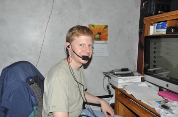
Fit is okay, but the wires pull down on the frame pulling the mic up. I need to get some foam tubing to put around the back to help push it off my head and rotate back into position. I think when I do it again, I'll leave the headset separate and just shrink wrap the mic wire to it. That will probably work better. Also, I'll likely use a solder board to attach everything to make the wiring neater in the box. Otherwise, it worked out well. I did get to test it in Ric Lee's Berkut on the ground and I was able to transmit and receive, so success! I'll find out how they do with noise at the Rocky Mountain Rendezvous in a couple of weeks and get some pictures of it in action.
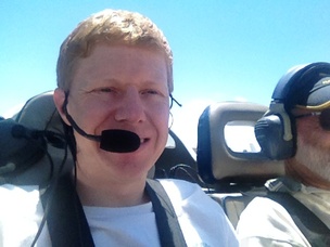
UPDATE: I got to fly with the headset a couple of times at the Canard Rendezvous at KFLY. The headset worked great from what I could tell. Voice was clear and the sound attenuation seemed just fine. I didn't have time to try the headset and a standard cup style side by side, but at the very least it was sufficiently working for me. It was plenty comfortable though it was a short flight. Long trips will be another thing, but compared to having a squeezing headset I can't image it would be worse. I'll be enjoying it!
